Alarm system – Grass Valley Trinix NXT v.3.3.1 User Manual
Page 67
Trinix NXT — Installation and Service Manual
67
Trinix Frames
Alarm System
The operation of cooling fans, frame power supplies, on-board power sup-
plies, and primary vs. secondary Broadlinx boards are all monitored. Any
alarm for these critical items is treated as a Primary alarm. With the release
of Broadlinx 3.1, the router’s system alarm has two modes, “No alarms”
and “Primary alarm.” All alarms (multiple fan failure, power supply
failure, etc.) are considered Primary alarms. All major components include
a local alarm LED.
The master alarm indicator is on the front panel (Power/Alarm) where
green indicates normal operation and red indicates a Primary alarm.
Symmetrical Frame
The rear panel Alarm BNC is configured to report primary alarms only. The
TRX-NXT-128x128 and TRX-NXT-256x256 is configured via jumper on the
NR/SR-33000 board. The location of the board is shown in
and
. The TRX-NXT-512x512 is configured
via a jumper on the RP-33500 512 x 512 Rear Panel board as shown on
The Alarm BNC for the TRX-NXT-256x512 version is configured the same
as the TRX-NXT-128x128 or TRX-NXT-256x256. In other words, through
the jumper on the NR-33000 board. See
Note
Secondary alarms are no longer supported.
Fan and Power Supply alarm status is concentrated on the SC board and is
reported through the OPM board for the Asymmetrical frames. The Power
Supply alarms are configured with the dual in-line package (DIP) switches
on the SC boards. (See Configuration DIP Switches
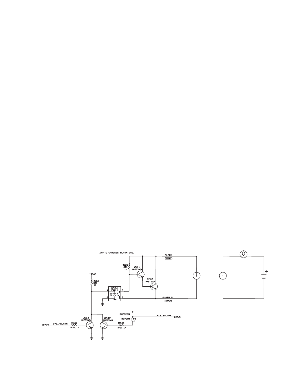
Figure 28. Rear Panel Master Alarm Circuit (left) and Example Of Customer-supplied Indicator
Circuit (right)
.
EXTERNAL CIRCUIT
(EXAMPLE)
NOT TO EXCEED
24 VDC @ 20 mA
REAR PANEL BNC