Grass Valley Trinix NXT v.3.3.1 User Manual
Page 316
316
Trinix NXT — Installation and Service Manual
Section 6 — Broadlinx Software
TRX-NXT-512x512 Routing switchers
1.
Connect to the Routing switcher following the procedure described on
2.
Click on the graphic of the Routing switcher front panel.
3.
Click “Signals”
A menu similar to
will then appear.
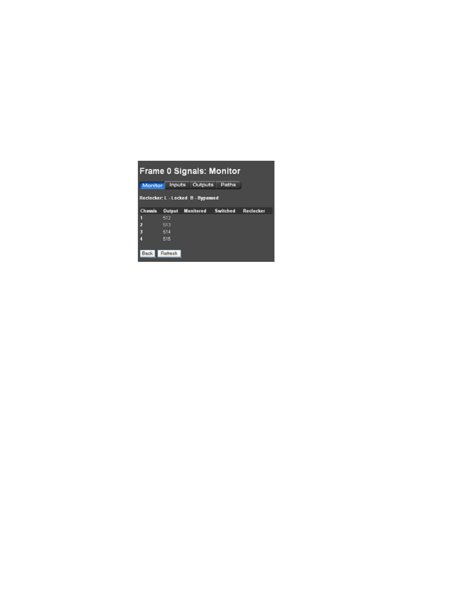
Figure 232.
Monitor Window (TRX-NXT-512x512).
The Monitor tab displays the following:
Chassis
: This column lists the monitor output ports labeled “1” through
“4” on the back of the frame.
Output
: This column lists the numbers that are entered in the control
system (for example, Jupiter) to identify the Trinix monitor outputs.
These numbers correspond to monitor output ports labeled 1 through 4 on
the rear of the frame (as shown in
).
Monitored
: This column lists the number of the output that is being moni-
tored by the control system.
Switched
: This column lists the number of the input that is being switched
to this monitor output.
Reclocker:
(TRX-NXT-256x256 and TRX-NXT-256x256), this column lists
the following:
•
“H” = The monitor output board is locked to (and is reclocking) an
HD signal.
•
“S” = The monitor output board is not reclocking this signal
(because the signal is either SD or Force Bypass mode is selected).
For more information about output monitor reclocking see Output
Monitor Reclock / Force Bypass Settings
.