Grass Valley Trinix NXT v.3.3.1 User Manual
Page 249
Trinix NXT — Installation and Service Manual
249
The 256X512 Trinix Asymmetrical Frame
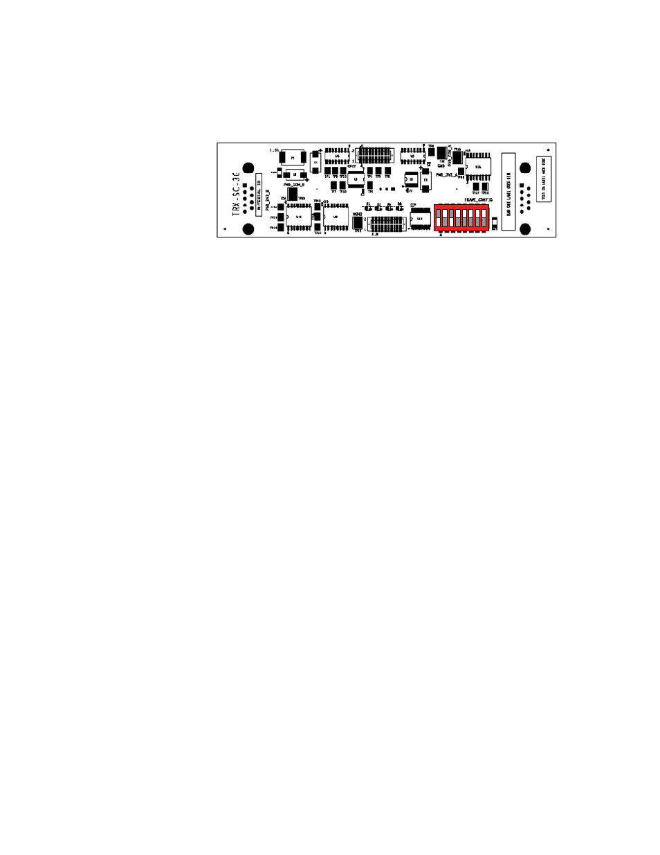
The corresponding TRX-SC DIP switch setting for the 256X512 redundant
power supply configurations, option C, is shown in
Figure 159. TRX-SC DIP Switch Settings for 256X512 Option C
The 256X512 Redundant Power Supply Configurations - Options D and E
The D and E configuration options for the redundant power supply
includes two Trinix power supply frames and six or eight power supply
modules.
One of the Trinix power supply racks is connected to the DC INPUT A con-
nector of the router frame. The power supply’s interface cable from this
Trinix power supply rack is connected to the PMBUS A connector of the
router frame.
The other Trinix power supply rack is connected to the DC INPUT B con-
nector of the router frame. The power supply’s interface cable from this
Trinix power supply rack is connected to the PMBUS B connector of the
router frame.
1
2
3
4
5
6
7
8
O
N
071827609_TRX-SC DIP Switch settings
for 128X256 Op