Own in, Figure 119 – Grass Valley Trinix NXT v.3.3.1 User Manual
Page 209

Trinix NXT — Installation and Service Manual
209
Output Monitoring
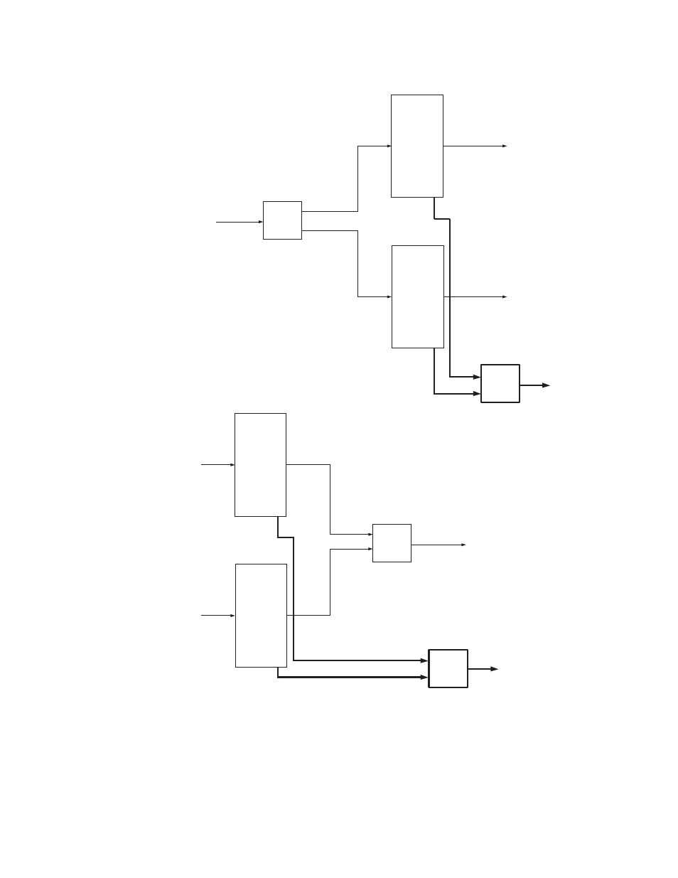
Figure 119. Monitoring with Input-expanded System
For all expanded systems with Monitoring, the “B” switch on the rear of the
frame must be set to ON (closed). See
(128 x 128);
x 256); or
(512 x 512).
The “Monitor” switch must also be set to identify the total number of
outputs (see page 203).
Trinix
Frame 0
256 x 256
1 - 256
1 - 256
257 - 512
1 - 256
1 - 256
PE-33016s
used as
splitters
PE-33016
used as
combiner
Output monitor video
Output monitor video
QC station
Trinix
Frame 2
256 x 256
Trinix
Frame 0
256 x 256
1 - 256
1 - 256
257 - 512
257-512
1 - 256
PE-33016s
32
used as
combiners
PE-33016
used as
combiner
Dual outputs
Output monitor video
QC station
Trinix
Frame 1
256 x 256
This manual is related to the following products:
