Board representation key, Input clocking – Grass Valley PROFILE FAMILY v.2.5 User Manual
Page 97
Input Clocking
Profile Family
97
The video references shown in the Input Clocking tab—Video Input 1–4 —
correspond to the actual video boards installed, from left to right, as represented
at the bottom of the Configuration Manager window.
For example, a system that does not use all four available clock references
might be configured like this. In this specific example, shown in Table 4, you
have one analog composite board and one component analog board. The panel
in the tab shows System, Video Input 1, and Video Input 2.
In the next example, a system that uses all four available clock references might
be configured with two serial digital component boards. In this specific
example, shown in Table 5, the panel in the tab shows System, Video Input 1,
Video Input 2, Video Input 3, and Video Input 4.
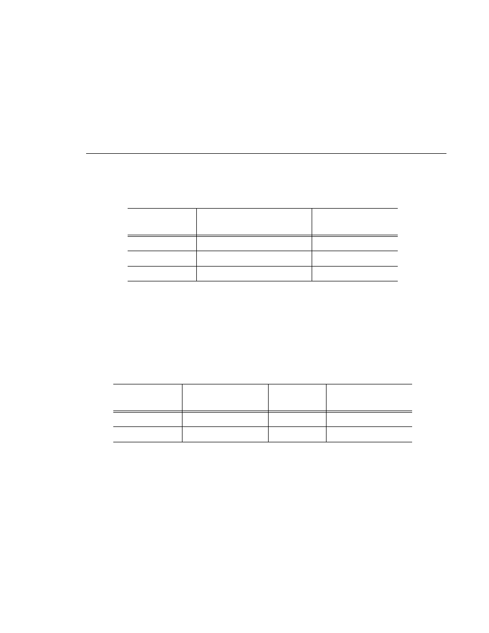
Table 3. Board representation key
Board Tag
Board Type
No. of Video
References
Vid I/O SDI VA
Serial digital component video
2
Vid I CAV
Component analog video
1
Vid I Cmpst
Analog composite video
1
Table 4. Configuration example, two video input clocking sources
Board Tag
Board Type
Board
Reference
Input Clock Reference
Vid I CAV
Component analog video
1
Video Input 1
Vid I Cmpst
Analog composite video
1
Video Input 2