Measurement Computing TempScan/1100 User Manual
Page 82
4-24 System Configuration
879596
TempScan / MultiScan User's Manual
Example 12g. Scan Alarm Stamping Enabled
(1)
PRINT#1, “OUTPUT07;A#1X”
(2)
(Command lines to configure and start an acquisition.)
(3)
PRINT#1, “OUTPUT07;R1X”
(4)
PRINT#1, “ENTER07”
(5)
INPUT A$
+0234.20 -0019.40 +0001.40 +0023.60 005 128 032 066
The above program example demonstrates how to enable alarm stamping:
• Line 1: Enable alarm stamping.
• Line 2: Provide the appropriate command lines to configure and start an acquisition.
• Line 3: Request the next scan in the buffer.
• Line 4: Retrieve the scan.
• Line 5: The screen will show the scan data in the buffer, stamped with the alarm output states.
Example 12h. Scan Alarm Stamping Disabled (Default)
(1)
PRINT#1, “OUTPUT07;A#0X”
(2)
(Command lines to configure and start an acquisition.)
(3)
PRINT#1, “OUTPUT07;R1X”
(4)
PRINT#1, “ENTER07”
(5)
INPUT A$
+0234.20 -0019.40 +0001.40 +0023.60
The above program example demonstrates how to disable alarm stamping:
• Line 1: Disable alarm stamping.
• Line 2: Provide the appropriate command lines to configure and start an acquisition.
• Line 3: Request the next scan in the buffer.
• Line 4: Retrieve the scan.
• Line 5: The screen will show the scan data in the buffer, without an alarm stamp.
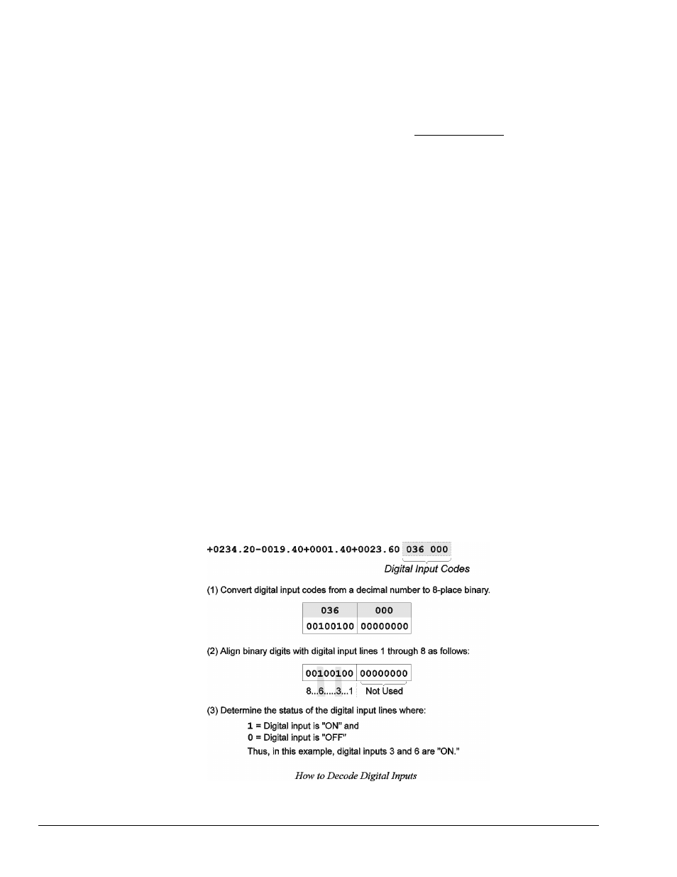
Digital Input Stamping
Note: In an 8-bit byte, Bits 00 through 07 correspond to digital input/output (DIO) lines 1 through
8. Also, Bit n corresponds to the decimal value 2^n (where n is an integer from 00 to 07).
The Set Digital Input Stamping (
I#
) command allows you to see whether a digital input was “active” or
“inactive” at the time of the scan. This is accomplished by appending a digital input on/off code to the
scan.