Measurement Computing TempScan/1100 User Manual
Page 81
TempScan / MultiScan User's Manual
879596
System Configuration 4-23
Example 12f. Scan Time Stamping Disabled (Default)
(1)
PRINT#1, “OUTPUT07;*T0X”
(2)
PRINT#1, “OUTPUT07;R3X”
(3)
PRINT#1, “ENTER07"
(4)
INPUT A$
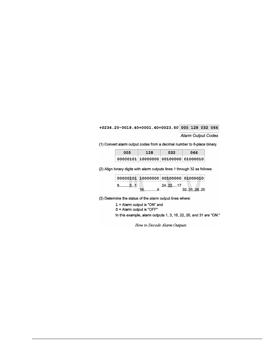
+0234.20 -0019.40 +0001.40 +0023.60
The above program example demonstrates how to disable time stamping:
• Line 1: Disable time stamping.
• Line 2: Request all scan data in buffer.
• Line 3: Retrieve the data.
• Line 4: The screen will show the scan data in the buffer, without a time stamp.
Scan Alarm Stamping
Note: In an 8-bit byte, Bits 00 through 07 correspond to digital input/output (DIO) lines 1 through
8. Also, Bit n corresponds to the decimal value 2^n (where n is an integer from 00 to 07).
As a further option in the monitoring and analysis of alarm conditions, the states of the 32 digital alarm
outputs can be stamped to each scan in real time.
Alarm stamping of each scan can be enabled with the Set Scan Alarm Stamping (
A#
) command. For more
information, see command Set Scan Alarm Stamping (
A#
) in Appendix A - API Command Reference.
Note: With MultiScan/1200 only, alarm stamping is not valid in single-channel high-speed burst
mode, since alarms are not monitored.
Note: If digital input stamping has also been enabled via the Set Digital Input Stamping (
I#
)
command, then the digital input states will be stamped after the alarm output states have been
stamped.