Hardware setup, Tempscan/multiscan quick start guide, P/n 446-0940) – Measurement Computing TempScan/1100 User Manual
Page 11: Tempscan / multiscan, Quick start guide, High-speed temperature & voltage systems
446-0940,
rev
2.2
988892
TempScan / MultiScan Quick Start Guide QS-1
TempScan / MultiScan
Quick Start Guide
High-Speed Temperature & Voltage Systems
Reference Note: Adobe PDF versions of user manuals will automatically install onto your hard drive as a part of
product support. The default location is in the Programs group, which can be accessed from the Windows Desktop
Start menu. Refer to the PDF documentation for details regarding both hardware and software. Note that PDF
versions of the documents can also be accessed directly from the data acquisition CD via the <View PDFs> button
located on the CD’s opening screen.
Minimum System Requirements
PC system with Pentium
®
Processor
Windows 2000 or /XP
64 Mbytes RAM
o This quick start covers connecting a TempScan/1100 or a MultiScan/1200 to the host computer’s
RS-232 serial port and configuring the device for RS-232 serial operation.
o Because you will be using ChartView, an “out-of-the-box” Windows-based data acquisition program,
no programming is required.
Note: Throughout the remainder of this document the term “scan device” refers to both the TempScan/1100 and to the
MultiScan/1200 data acquisition device.
Hardware Setup
Step 1: Check the Voltage Setting
Based on your order, your scan device was set at the voltage indicated on the sticker located on the rear panel of the unit
(near the power switch): 105-125 or 210-250 volts AC. Verify that the voltage value indicated on the sticker matches the
voltage of your intended AC power supply. If you need to change the AC power line selection for any reason, refer to the
chapter Power & Assembly in your user's manual.
Step 2: Set the Operation Mode via DIP Switch
The scan device is default configured for IEEE 488 port connection to a PC. To configure the unit for RS-232 serial
operation, change the DIP switch setting as indicated in the following table and figure. Otherwise, to configure the unit for
RS-422 serial operation or IEEE 488 operation refer to chapter 1 in your TempScan/1100 & MultiScan/1200 user’s manual.
A PDF version of the manual is included on the data acquisition CD.
The DIP switch is located on the rear panel of your unit. One possible RS-232 serial setting is indicated in the following
figure and table. We make use of this serial setting in this Quick Start Guide. For alternative serial settings, refer to chapter
1 in your TempScan/1100 & MultiScan/1200 user's manual.
DIP Switch
Configuration
One of many possible settings for RS-232 Serial Communication*
Selection
Micro-switch
Setting
COMM SELECT
1
1- RS-232
HANDSHAKE (H/S)
2,3
00 - No Handshake
PARITY
4,5
00 - No Parity
BAUD RATE
6,7,8
101 - 9600 Baud
CALIBRATION
9
0 - Disabled
*Refer to the user’s manual in regard to other configurations.
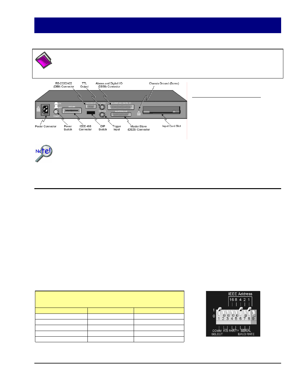
Rear Panel, Applies to both TempScan and MultiScan
DIP Switch (on Rear Panel)
Set for RS-232 Serial, see table at left.