Set digital outputs – Measurement Computing TempScan/1100 User Manual
Page 242
A-46 API Command Reference
889897
TempScan / MultiScan User’s Manual
O
- Set Digital Outputs
TYPE
System
EXECUTION
Immediate
SYNTAX
Obank1,
bank2,
bank3,
bank4
Set any of the 32 digital outputs, grouped into four 8-bit banks, to a specified
setting, where
bankn
(for
n
=
1
,
2
,
3
,
4
) is an argument in the form of the
number
nnn
such that
000
<
nnn
<
255
when converted to binary format
represents the desired settings for the 8-bit bank.
O?
Query current state of digital output.
DESCRIPTION
Located on the TempScan/1100 or MultiScan/1200 rear panel, the DB50 digital I/O connector provides eight (8)
digital input lines and thirty-two (32) digital output lines. The Set Digital Outputs (
O
) command allows you to force
any of the 32 digital outputs, grouped into four 8-bit banks, to a specific setting. For each digital output, you can
specify whether the bit should be cleared with a
0
(active low, logic
false
) or set with a
1
(active high, logic
true
).
The Set Digital Outputs (
O
) command will override the current alarm output status as set via the Assign Alarm
Output (
A
) command. However, if it is desired not to affect a certain bank (for example, to preserve the alarm
output states), a value of
999
can be used for the argument for that bank. This will effectively “mask off” that
bank from being updated.
The Bank to Digital Output mapping is as follows:
Bank 1 (Byte 1): Digital Outputs (Bits) 07 through 00.
Bank 2 (Byte 2): Digital Outputs (Bits) 15 through 08.
Bank 3 (Byte 3): Digital Outputs (Bits) 23 through 16.
Bank 4 (Byte 4): Digital Outputs (Bits) 31 through 24.
Each argument
bankn
represents the desired bitmapping for the corresponding bank of digital outputs. The
argument is a decimal number, which, when converted to binary format, represents the desired settings for that
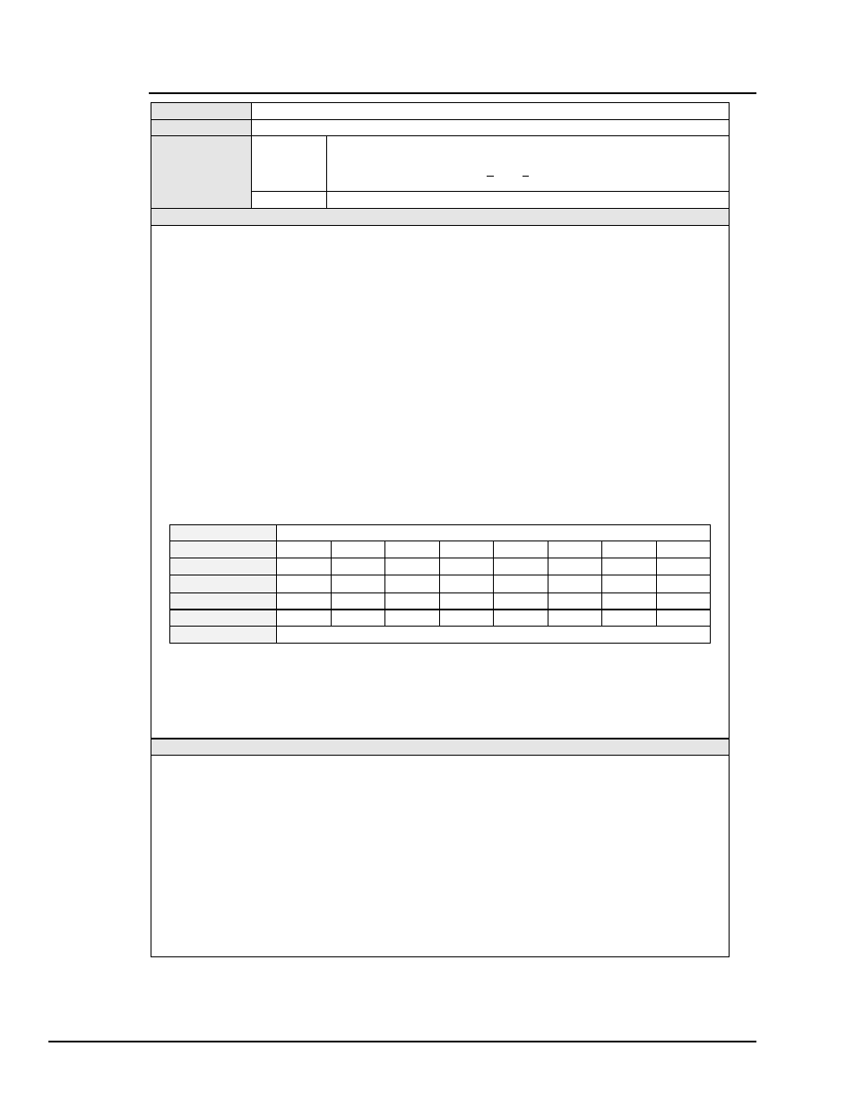
bank of digital outputs. For example, an argument of
201
for
bank2
would be interpreted in binary as
11001001
as follows:
Argument
201 = 128 + 64 + 8 + 1
Decimal Values
128
64 0 0 8 0 0 1
Active High/Low
High High Low Low High Low Low High
Logical Value
1 1 0 0 1 0 0 1
Bit
15 14 13 12 11
10 09 08
Digital I/O Line
16 15 14 13 12
11 10 09
Digital Outputs
Digital Outputs Lines 16, 15, 12 and 09 are set.
For more information on digital outputs, see section Digital I/O Configuration in the chapter TempScan/1100 &
MultiScan/1200, or see section Digital I/O Configuration in the chapter System Configuration.
Note: In an 8-bit byte, Bits 00 through 07 correspond to digital input/output (DIO) lines 1 through 8. Also, Bit n
corresponds to the decimal value 2^n (where n is an integer from 00 to 07).
EXAMPLE
PRINT#1, “OUTPUT07;O?X”
‘ Get the current state of the digital output banks
PRINT#1, “ENTER07”
LINE INPUT #2, N$
PRINT N$
O128,255,065,024
‘ Screen shows the current state of the banks
PRINT#1, “OUTPUT07;O000,999,076,234X”
‘ Set Banks 1, 3, and 4
PRINT#1, “OUTPUT07;O?X”
‘ Get the new state of the digital output banks
PRINT#1, “ENTER07”
LINE INPUT #2, O$
PRINT O$
O000,255,076,234
‘ Screen shows the new state of the banks
‘ Note that Bank 2 did not change