Calibration protection configuration, Digital i/o configuration, Caution – Measurement Computing TempScan/1100 User Manual
Page 27
TempScan / MultiScan User’s Manual
899493
System Overview 1-13
• Clear To Send Positive (CTS+): This input pin is used as a hardware handshake line to prevent the
TempScan/1100 or MultiScan/1200 unit from transmitting serial data to an RS-232 or RS-422 device
when it is not able to accept it. When RTS/CTS handshaking is selected, the unit will not Transmit
Data (TxD+) out while the CTS+ signal is un-asserted (low). When XON/XOFF or no handshaking is
selected, the CTS+ line is ignored.
• Clear To Send Negative (CTS-): This input pin is used as a hardware handshake line with an RS-422
device only. It functions identically to CTS+ except that its polarity is inverted. This signal is low true.
• Ground (GND): This signal sets the ground reference point for the other RS-232/RS-422 input and
output signals.
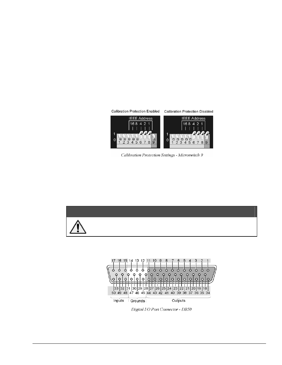
Calibration Protection Configuration
The chassis calibration constants and the calibration password are stored by the TempScan/1100 or
MultiScan/1200 in Non-Volatile RAM (NV-RAM). The password is a safety feature used to prevent
unauthorized personnel from entering calibration mode and altering the calibration constants.
As a safeguard, the calibration password and chassis calibration constants are hardware protected.
This protection is enabled by setting the microswitch 9 to the down (0) position on the rear panel DIP
switch. This is the default factory setting and should remain in this position unless purposely attempting to
change the password or chassis constants.
If it is necessary to change the calibration password (via the
*K
command) or to recalibrate the chassis, this
hardware write protection can be disabled by setting microswitch 9 to the up (1) position. For details on
calibration, see chapter System Calibration.
CAUTION
Do not forget to set back the DIP microswitch 9 to the down (0) position when
calibration is complete. Otherwise, the calibration password and calibration
constants may be corrupted and normal operation may be disrupted.
Digital I/O Configuration
Located on the TempScan/1100 or MultiScan/1200 rear panel, the DB50 digital I/O connector provides
eight (8) digital input lines and thirty-two (32) digital output lines. The figure and table locate and describe
the input, output, and ground lines of this connector.