Caution – Measurement Computing TempScan/1100 User Manual
Page 79
TempScan / MultiScan User's Manual
879596
System Configuration 4-21
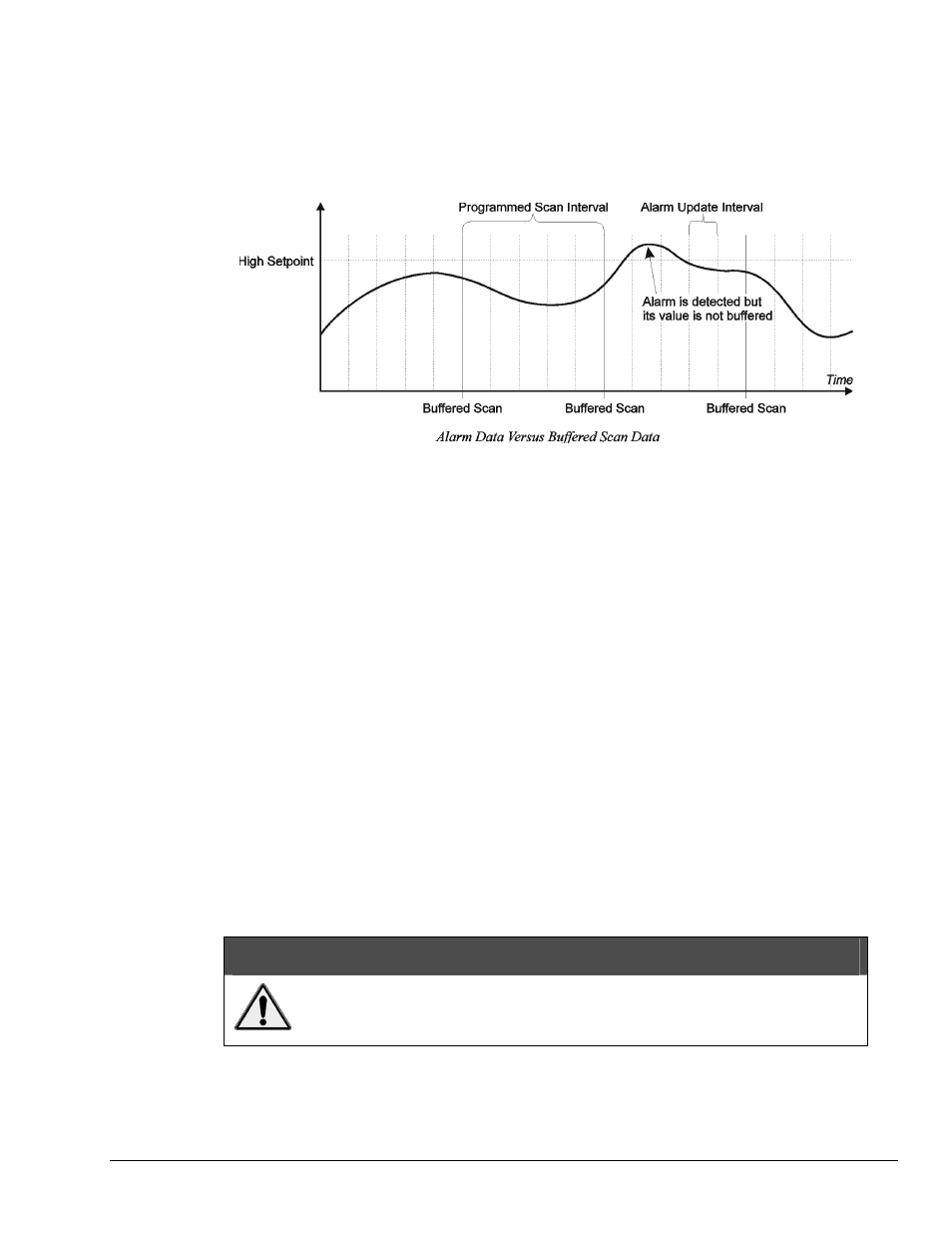
Comparing Buffered Data to Alarm Status Data
With the TempScan/1100 unit, unless scans are being collected at the maximum possible frequency, the
alarm system may detect alarm states that will not appear in the collected data. Since the alarms are being
updated at the maximum possible frequency, which may be considerably faster than the scan frequency as
set by the programmed scan interval, an alarm state may be detected even though no such value can be
found in the buffered scan data.
If such a situation is not preferred, decreasing the programmed scan interval (thus increasing the scan
frequency) will decrease the possibility of such an event. At the maximum possible scan frequency, this
situation is guaranteed not to occur.
With the MultiScan/1200 unit, the alarms are being updated at the same frequency as set by the
programmed scan interval. Hence, all detected alarm states will appear in the collected data.
Digital I/O Configuration
Located on the TempScan/1100 or MultiScan/1200 rear panel, the DB50 digital I/O connector provides
eight (8) digital input lines and thirty-two (32) digital output lines. The digital output can be controlled
either via the alarm settings or via the Set Digital Outputs (
O
) command. To query the digital output state,
use the Set Digital Outputs (
O
) command.
The Set Digital Outputs (
O
) command allows you to force any of the 32 digital outputs, grouped into four
8-bit banks, to a specific setting. For each digital output, you can specify whether the bit should be cleared
with a
0
(active low, logic
false
) or set with a
1
(active high, logic
true
). This command will override
the current alarm output status as set via the Assign Alarm Output (
A
) command.
Each digital output line will drive five (5) standard TTL (transistor-transistor logic) loads. All digital input
lines are one-eighth (0.125) TTL loads. All inputs are protected against damage from high static voltage.
Normal precautions should be taken to limit the input voltages to the range of 0.0 to 5.3 volts. All digital
I/O lines are referenced to digital ground.
For more information on digital I/O, see section Digital I/O Configuration in Chapter 1, System Overview,
and the Set Digital Outputs (
O
) command in Appendix A-API Command Reference.
CAUTION
Do not exceed the levels described. Otherwise, the TempScan/1100 or
MultiScan/1200 unit may be damaged in a way that is not covered by the
warranty.