Rear panel switches & connectors – Measurement Computing TempScan/1100 User Manual
Page 17
TempScan / MultiScan User’s Manual
899493
System Overview 1-3
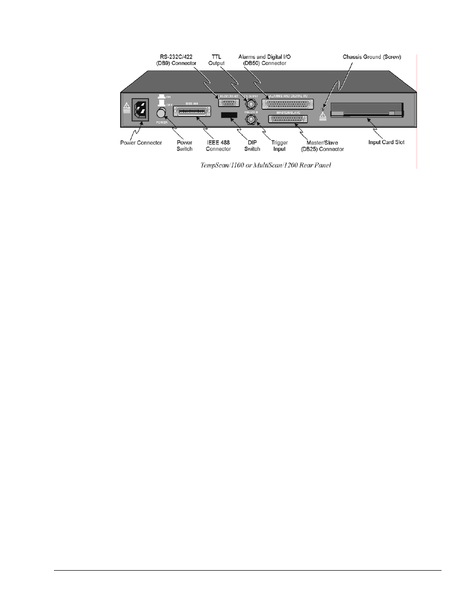
Rear Panel Switches & Connectors
Two (2) switches, seven (7) connectors, one (1) grounding nut, and one (1) input card slot on the rear panel
of either the TempScan/1100 or MultiScan/1200 provide power, IEEE 488 addressing, triggering, a single
point grounding node, and I/O connections.
Power Switch
Used to turn power to the unit ON and OFF. When the switch is in
the depressed position the power is ON. When in the extended
position, the power is OFF.
DIP Switch
For IEEE 488: Used for selecting IEEE 488 communication and bus
address.
For RS-232: Used for selecting RS-232 serial
communication, handshaking, parity and baud rate.
Microswitch 9 is used to enable/disable the hardware
protected portion of NV-RAM.
Power Connector
Provides power for the unit. Internally configurable for either 105-
125 or 210-250 VAC, 50/60Hz, plus fuse circuit breaker.
IEEE 488 Connector
Port for the IEEE 488 interface.
RS-232C Connector
DB9 serial port for operation at remote distances from controlling
computer supports 300 to 9,600 baud using RTS/CTS or
XON/XOFF handshaking (XON/XOFF for ASCII transmissions
only).
TTL Output Connector
BNC TTL scan output signal occurs for each channel scan; used for
synchronizing other equipment with TempScan/1100 or
MultiScan/1200 acquisition.
Trigger Input Connector
BNC trigger input for starting and/or stopping acquisition of the
TTL output signal.
Alarms & Digital I/O Connector
DB50 port offers easy access to Alarms and Digital I/O
(32 digital outputs and 8 digital inputs)
Master/Slave Connector
DB25 master/slave port connects to Exp/10A and/or Exp/11A
expansion slave units to support applications of up to 992 channels
with the TempScan/1100 master unit, or up to 744 channels with the
MultiScan/1200 master unit.
Grounding Screw
An external single-point grounding node has been supplied for (but
not limited to) thermocouple shield termination.