Measurement Computing TempScan/1100 User Manual
Page 26
1-12 System Overview
899493
TempScan / MultiScan User's Manual
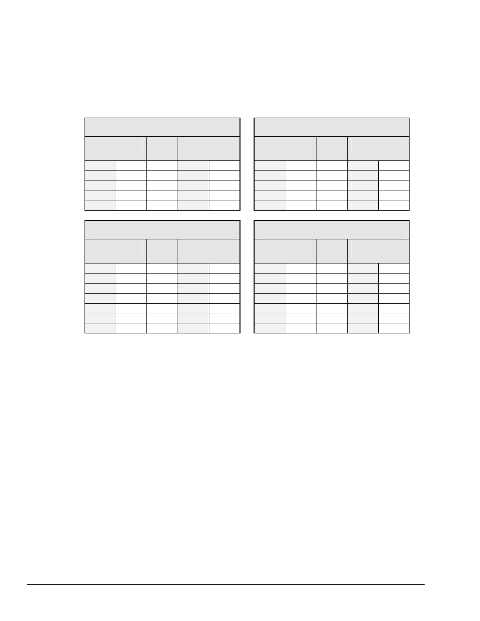
A CA-47 cable connects the unit with the computer. The TempScan/1100 or MultiScan/1200 end has one
DB9 connector, and the computer end has two connectors – one for a DB9 and one for a DB25. O
ther crossover-type cables can be used if they are wired as shown in the tables. The tables list the
following four connections from the TempScan/1100 or MultiScan/1200 unit:
• To a DB9 connector configured for RS-232
• To a DB25 connector configured for RS-232
• To a DB9 connector configured for RS-422
• To a Mini DIN8 connector configured for RS-422.
TempScan/1100 or MultiScan/1200
To PC Connection (RS-232)
TempScan/1100 or MultiScan/1200
To PC Connection (RS-232)
DB9 Male
Pin & Signal
Cable
Wirin
g
DB9 Female
Pin & Signal
DB9 Male
Pin & Signal
Cable
Wirin
g
DB25 Female
Pin & Signal
2 RxD-
←--
3 TxD-
2 RxD-
←--
2 TxD-
3 TxD- --
→
2 RxD-
3 TxD- --
→
3 RxD-
5 GND
←→
5 GND
5 GND
←→
7 GND
7 RTS+ --
→
8 CTS+
7 RTS+ --
→
5 CTS+
8 CTS+
←--
7 RTS+
8 CTS+
←--
4 RTS+
TempScan/1100 or MultiScan/1200
To Macintosh Connection (RS-422)
TempScan/1100 or MultiScan/1200
To Macintosh Connection (RS-422)
DB9 Male
Pin & Signal
Cable
Wirin
g
DB9 Male
Pin & Signal
DB9 Male
Pin & Signal
Cable
Wirin
g
Mini DIN8 Male
Pin & Signal
1 GND
←→
3 GND
1 GND
←→
4 GND
2 RTS+ --
→
7 CTS+
2 RTS+ --
→
2 CTS+
4 TxD+ --
→
8 RxD+
4 TxD+ --
→
8 RxD+
5 TxD- --
→
9 RxD-
5 TxD- --
→
5 RxD-
6 CTS+
←--
6 RTS+
6 CTS+
←--
1 RTS+
8 RxD+
←--
4 TxD+
8 RxD+
←--
6 TxD+
9 RxD-
←--
5 TxD-
9 RxD-
←--
3 TxD-
The following text describes the various pin connector signals:
• Transmit Data Negative (TxD-): This output pin transmits serial data to an RS-232 or RS-422 device.
The serial data received is sent with the word length, baud rate, stop bits, and parity configured for the
particular port. This signal is low true.
• Transmit Data Positive (TxD+): This output pin transmits serial data to an RS-422 device only.
The pin functions identically to TxD- except that its polarity is inverted. This signal is high true.
• Receive Data Negative (RxD-): This input pin accepts serial data sent by an RS-232 or RS-422 device.
The serial data received is expected to match the word length, baud rate, stop bits, and parity
configuration of the particular port. This signal is low true.
• Receive Data Positive (RxD+): This input pin accepts serial data sent by an RS-422 device only.
It functions identically to RxD- except that its polarity is inverted. This signal is high true.
• Request To Send Positive (RTS+): This output pin is used as a hardware handshake line to prevent an
RS-232 or RS-422 device from transmitting serial data to the TempScan/1100 or MultiScan/1200 unit
when it is not able to accept it. When automatic RTS/CTS handshaking is selected, the unit will assert
(high) the RTS+ signal when greater than 4096 memory locations are available in its internal buffers. If
available memory drops below 4096 bytes, the unit unasserts (low) the RTS+ signal.
• Request To Send Negative (RTS-): This output pin is used as a hardware handshake line with an
RS-422 device only. The pin functions identically to RTS+ except that its polarity is inverted. This
signal is low true.