System breaker configuration setting, Figure 36, Figure 37 – Basler Electric DGC-2020HD User Manual
Page 89: Figure 38, Load, Dgc-2020hd
9469300990 Rev B
79
Figure 36. System Breaker Configuration: Generator and Mains Breaker Control as Displayed in
BESTCOMSPlus System Settings
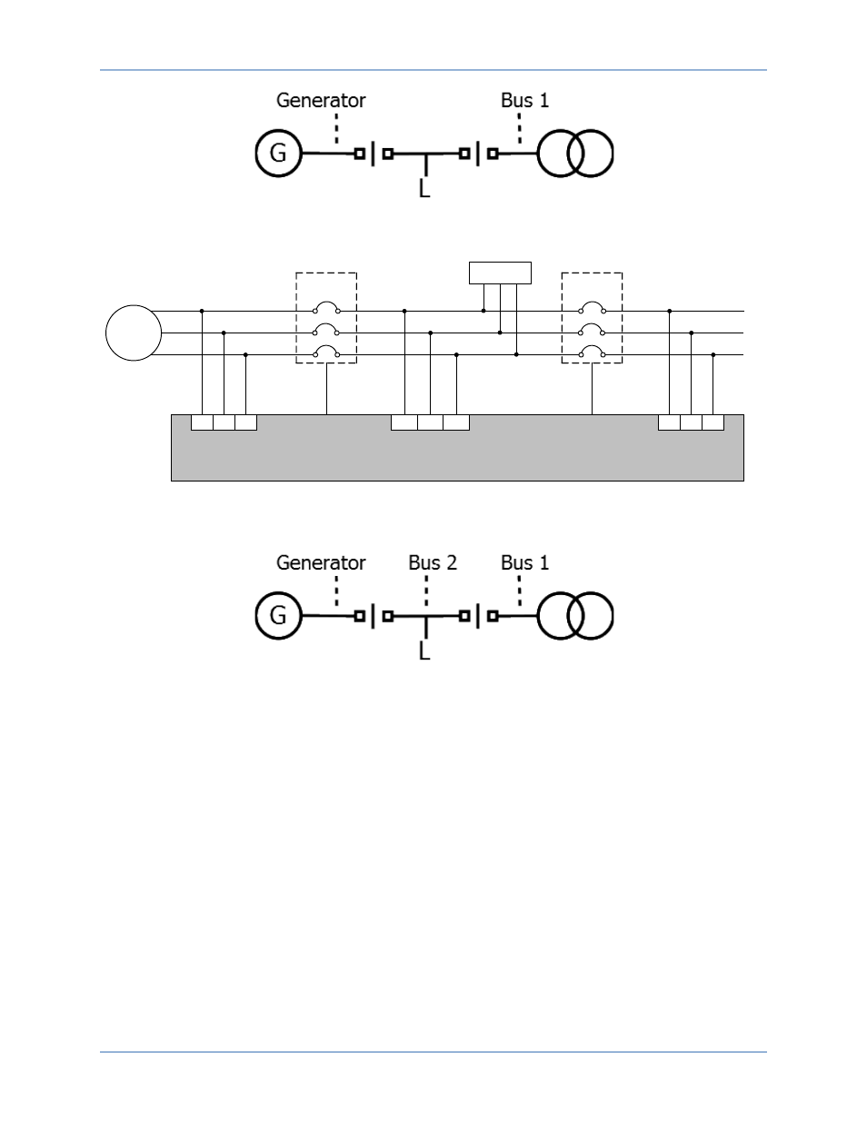
Figure 37. System Breaker Configuration: Generator and Mains Breaker Control with Optional Load Bus
Metering
Figure 38. System Breaker Configuration: Generator and Mains Breaker Control with Optional Load Bus
Metering as Displayed in BESTCOMSPlus System Settings
System Breaker Configuration Setting
BESTCOMSPlus
®
Navigation Path: Settings Explorer, System Parameters, System Settings
Front Panel Navigation Path: Settings Explorer > System Parameters > System Settings
Select the appropriate breaker control configuration using the System Breaker Configuration setting.
Available options include, No Breaker Control, Generator Breaker Control, Generator and Mains Breaker
Control, and Generator and Mains Breaker Control with Load Bus. In BESTCOMSPlus, a one-line
diagram is provided for each breaker configuration to aid in proper selection. Each bus can be
programmed with a text label describing its use. Up to 64 alphanumeric characters are accepted. This
label appears in BESTCOMSPlus to aid in ease of configuration and programming.
Generator
Generator
Breaker
L1
L2
L3
Generator Bus
Load Bus
Generator
Bus Metering
Load Bus
Metering
P0071-76
LOAD
Mains
Breaker
Mains Bus
Mains Bus
Metering
A
B
C
Generator
Breaker
Control Output
Mains Breaker
Control Output
86
88
90
103
101
100
93
95
97
Bus 2
Bus 1
DGC-2020HD
DGC-2020HD
Breaker Management