Table 24, N table 25 – Basler Electric DGC-2020HD User Manual
Page 64
54
9469300990 Rev B
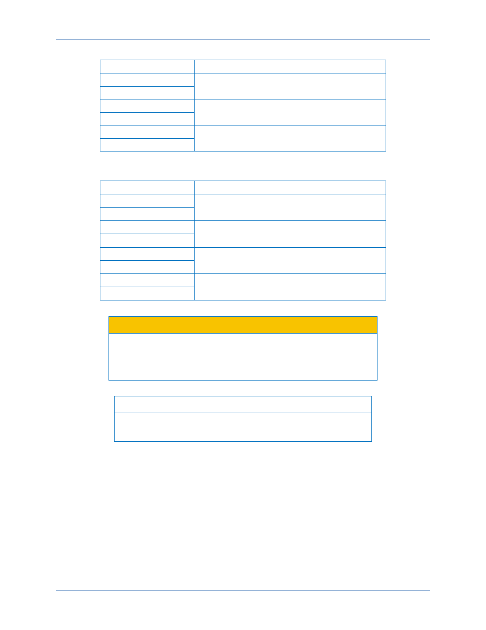
Table 24. Generator Current Sensing Terminals
Terminal
Description
1 (IA+
)
A-phase generator current sensing input
2 (IA–)
3 (IB+)
B-phase generator current sensing input
4 (IB–)
5 (IC+)
C-phase generator current sensing input
6 (IC–)
Table 25. Bus Current Sensing Terminals
Terminal
Description
7 (AUX I1+)
User-programmable current sensing input 1
8 (AUX I1–)
9 (AUX I2+)
User-programmable current sensing input 2
10 (AUX I2
–)
11 (AUX I3+)
User-programmable current sensing input 3
12 (AUX I3–)
13 (AUX I4+)
User-programmable current sensing input 4
14 (AUX I4–)
Caution
Generator current sensing terminals 2 (IA–), 4 (IB–), and 6 (IC–) and
user-programmable current sensing terminals 8 (AUX I1–), 10 (AUX I2–),
12 (AUX I3–), and 14 (AUX I4–) must be terminated to ground for proper
operation.
Note
Unused current sensing inputs should be shorted to minimize noise
pickup.
Voltage and Current Sensing
DGC-2020HD