Basler Electric DGC-2020HD User Manual
Page 126
116
9469300990 Rev B
proportionally decreased. Proportional correction pulses are beneficial in applications where fixed
correction pulses can result in overshooting the slip frequency and regulation offset targets.
When the bias control output type is set to analog, a PID controller controls the bias signal from the DGC-
2020HD to the speed governor. The controller adjusts the bias output to drive the error between desired
generator speed and measured generator speed to zero. Settings are provided for proportional gain,
integral gain, derivative gain, derivative filter constant, and loop gain of the PID controller.
The speed trim enable setting sets speed trimming to the speed trim setpoint when the generator breaker
is closed and the machine is not paralleled to the utility. If speed trimming is enabled in all generators in
an islanded system, it is ensured that the system will run at the speed trim setpoint. If it is not enabled in
any units, the islanded system may deviate from the speed trim setpoint, depending on the initial speed
settings of the isochronous governors. Speed trim should be enabled in all units or disabled in all units of
an islanded system. If it is enabled in only a subset of the units, speed trimming and load sharing may
conflict, resulting in unpredictable load sharing and system frequency.
After ramping a generator's kW output, to bring it online or offline, overshoot may occur. The likeliness of
kW overshoot increases as the ramp rate increases. Typically, overshoot is reduced by lowering the ramp
rate to the slowest possible setting. If overshoot is still a problem, the Ramp Overshoot Reduction setting
can be used. A setting of 0% overshoot reduction results in no change to the amount of overshoot. A
setting of 100% provides maximum overshoot reduction. Ramp Overshoot Reduction must be tuned to
the optimal level. Too little reduction may result in overshoot while too much reduction may result in
undershoot.
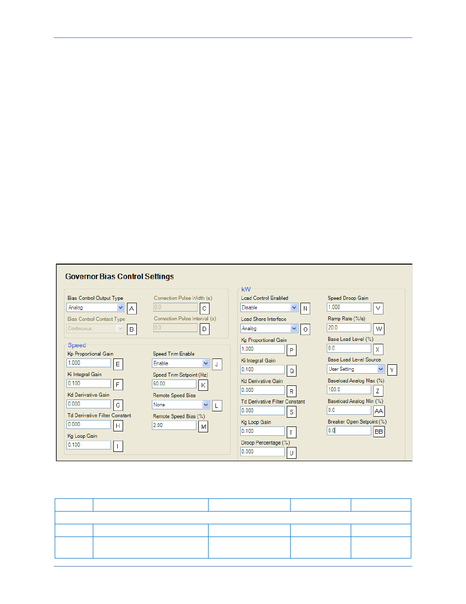
The BESTCOMSPlus Governor Bias Control Settings screen is illustrated in Figure 60. Settings are listed
in Table 38.
Figure 60. Settings Explorer, Bias Control Settings, Governor Bias Control Settings
Table 38. Settings for Governor Bias Control
Locator
Setting
Range
Increment
Unit
Panel Settings
A
Bias Control Output Type
Contact or Analog
n/a
n/a
B
Bias Control Contact Type
Continuous or
Proportional
n/a
n/a
Bias Control
DGC-2020HD