Logic connections, Operational settings – Basler Electric DGC-2020HD User Manual
Page 138
128
9469300990 Rev B
Per Unit
Settings which are related to machine ratings can be set in either actual units of voltage or in per unit
values. When a native unit is edited, BESTCOMSPlus automatically recalculates the per unit value based
on the native unit setting and the rated data parameter (on the System Parameters, Rated Data screen)
associated with it. Conversely, when a per unit value is edited, BESTCOMSPlus automatically
recalculates the native value based on the per unit setting and the rated data parameter associated with
it.
Once all per unit values are assigned, if the rated data parameters are changed, BESTCOMSPlus
automatically recalculates all native unit settings based on the modified rated data parameters.
The following settings have native units of Secondary Volts, and the rated data associated with them is
Rated Secondary Volts (on the System Parameters, Rated Data screen).
•
Undervoltage 27-x Three-Phase Pickup
•
Undervoltage 27-x Single-Phase Pickup
Low-Line Scale Factor
A low-line scale factor setting is used to automatically adjust the undervoltage pickup settings in
applications that might utilize more than one type of genset connection. The scale factor setting is
implemented when the DGC-2020HD is determined to be in a low-line configuration. If the Low-Line
Override function is assigned to a contact input via the Programmable Functions screen, the state of the
contact input and the detected configuration are ORed. This means, if one or both are true, then the
system is determined to be configured for low-line. The value of the scale factor setting serves as a
multiplier for the pickup settings. For example, if a scale factor contact input is received by the DGC-
2020HD and the scale factor setting is 2.000, the pickup setting will be doubled (2.000 x PU).
Alarm Configuration
An undervoltage annunciation can be user-selected to trigger a pre-alarm (warning) or alarm (shutdown).
It can also be user-configured to close a programmable output.
Element status is available in BESTlogicPlus programmable logic when “Status Only” is selected.
Inhibit Frequency
Inhibit Frequency impedes undervoltage element operation during undervoltage conditions that may occur
during equipment startup.
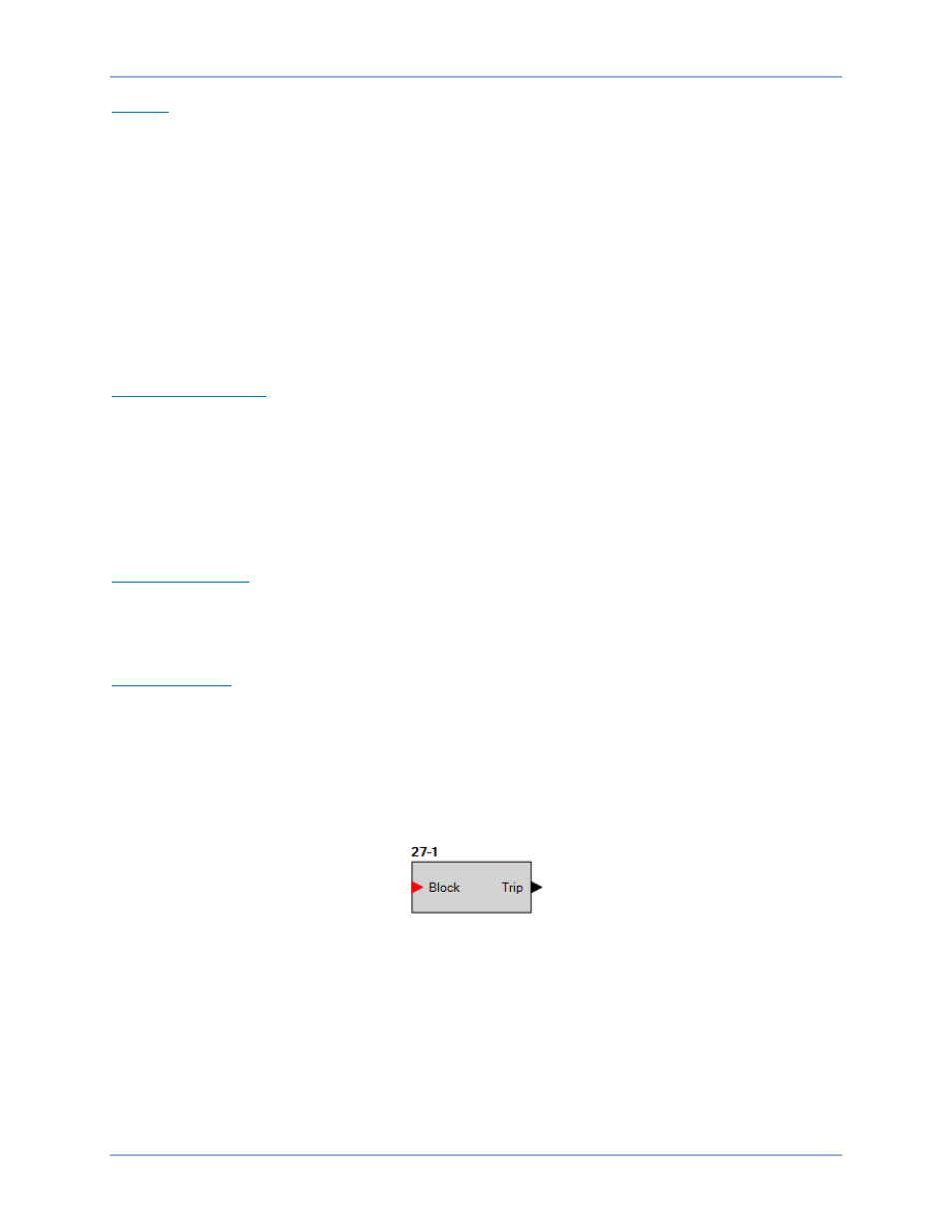
Logic Connections
Undervoltage element logic connections are made on the BESTlogicPlus screen in BESTCOMSPlus. The
undervoltage element logic block is illustrated in Figure 67. When the Block input is true, the 27 element
is disabled. The Trip output is true when the 27 element is in a trip condition.
Figure 67. Undervoltage Element Logic Block
Operational Settings
Undervoltage element operational settings are configured on the Undervoltage settings screen (Figure
68) in BESTCOMSPlus. Setting ranges are defined in the Specifications chapter.
Generator Protection
DGC-2020HD