Operational settings, Phase voltage imbalance (47), Element operation – Basler Electric DGC-2020HD User Manual
Page 141
9469300990 Rev B
131
Figure 69. Overvoltage Element Logic Block
Operational Settings
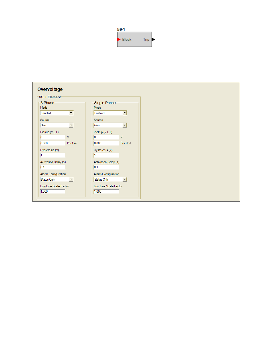
Overvoltage element operational settings are configured on the Overvoltage settings screen
(Figure 70) in BESTCOMSPlus. Setting ranges are defined in the Specifications chapter.
Figure 70. Settings Explorer, Generator Protection, Voltage, Overvoltage
Phase Voltage Imbalance (47)
Six phase voltage imbalance protection (47) elements monitor the sensing voltage applied to the DGC-
2020HD. An element can be configured to protect against voltage imbalances between any of the three
phases. This element is available only in styles xxExxxxxx of the DGC-2020HD.
The six, identical phase voltage imbalance protection elements are designated 47-1, 47-2, 47-3, 47-4,
47-5, and 47-6. Element logic connections are made on the BESTlogic
™Plus screen in BESTCOMSPlus®
and element operational settings are configured on the Phase Voltage Imbalance settings screen in
BESTCOMSPlus.
BESTCOMSPlus Navigation Path: Settings Explorer, Generator Protection, Voltage, Phase Imbalance
(47)
Front Panel Navigation Path: Settings Explorer > Protection > Settings Group x (where x = 0 to 3) >
Voltage Protection > Phase Volt Imbalance (47)
Element Operation
Phase voltage imbalance elements provide negative phase-sequence (V2) protection in a three-phase
system. The V2 measurement increases as voltage becomes unbalanced or the phase sequence is
reversed.
The Pickup setting entered is based on the PT secondary side (DGC-2020HD).
DGC-2020HD
Generator Protection