Breaker management, Breaker status, System breaker configuration – Basler Electric DGC-2020HD User Manual
Page 87: Initial system setup, Generator breaker control, Load, Dgc-2020hd
9469300990 Rev B
77
Breaker Management
DGC-2020HD breaker management features include the control of two, continuous- or pulse-controlled
breakers, load transfer upon detection of a mains failure, two modes of automatic genset synchronization,
and settings for stable or dead bus detection. Open transitions are implemented in load transfers to and
from the mains. The user can choose to control only the generator breaker, both breakers, or none at all.
Breaker management settings can be configured using BESTCOMSPlus
®
or through the front panel
interface.
Breaker Status
The status of the breakers is retrieved by properly setting up the GENBRK and MAINSBRK logic blocks in
BESTlogic™Plus programmable logic. These logic blocks have outputs that can be configured to close an
output contact which in turn controls a breaker. They contain inputs for breaker control and status as well.
See Breaker Configuration, below, for details on configuring the logic.
System Breaker Configuration
The following paragraphs describe how to properly configure DGC-2020HD system breaker control
configuration.
Initial System Setup
Connect the DGC-2020HD according to the appropriate figure in the Typical Applications chapter for the
type of generator connection desired (wye, delta, etc.). Set up the basic system parameters that will
govern engine operation and alarm and pre-alarm annunciation. Details can be found in the Configuration
and Reporting and Alarms chapters.
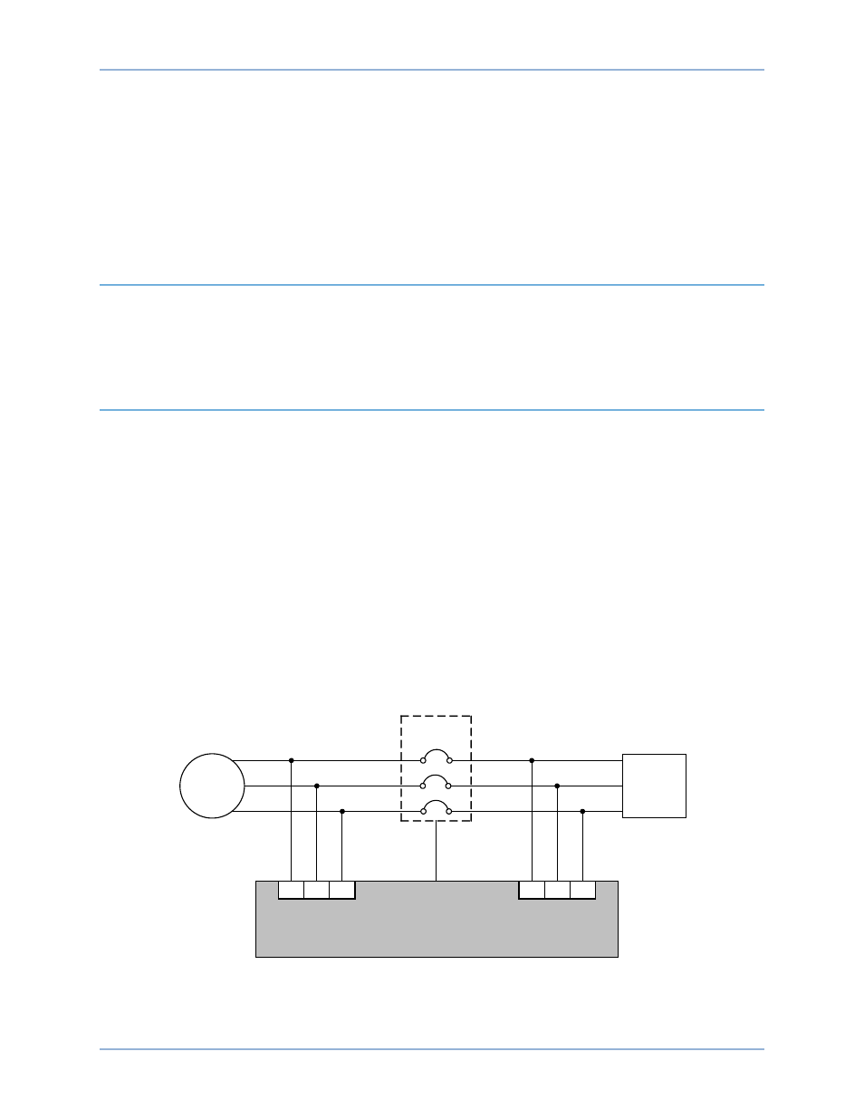
Generator Breaker Control
A system breaker configuration of Generator Breaker Control consists of a single generator breaker
controlled by the DGC-2020HD. Figure 32 illustrates the Generator Breaker Control system breaker
configuration. Figure 33 shows the Generator Breaker Control system breaker configuration with a mains
bus and externally controlled mains breaker. Figure 34 illustrates the one-line diagram of the Generator
Breaker Control configuration as it appears in the BESTCOMSPlus System Settings screen.
Figure 32. System Breaker Configuration: Generator Breaker Control
Generator
Generator
Breaker
L1
L2
L3
Generator Bus
Load Bus
Generator
Bus Metering
P0071-75
LOAD
Generator
Breaker
Control Output
86
88
90
93
95
97
Bus 1
DGC-2020HD
Load Bus
Metering
DGC-2020HD
Breaker Management