Example 2 - and gate connections, Example 3 - multiple logic connections – Basler Electric DGC-2020HD User Manual
Page 248
238
9469300990 Rev B
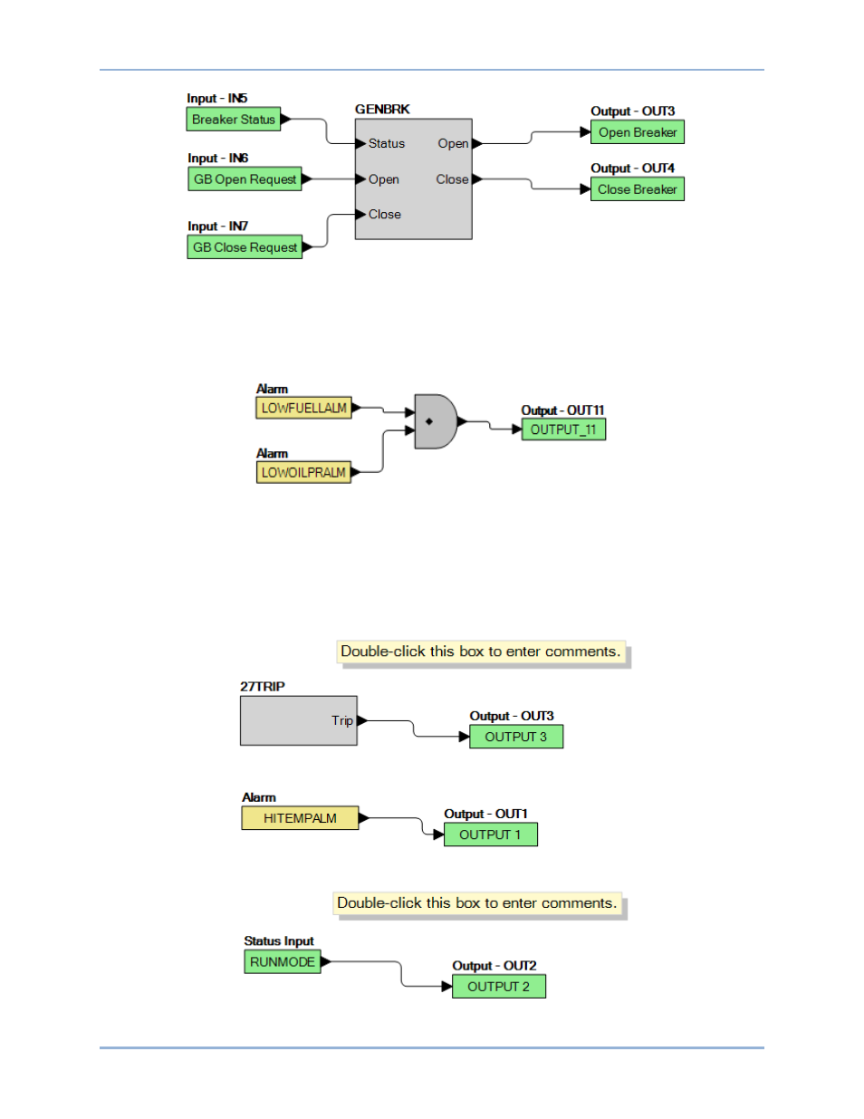
Figure 150. Example 1 – GENBRK Logic Block Connections
Example 2 - AND Gate Connections
Figure 151 illustrates a typical AND gate connection. In this example, Output 11 will become active when
the Low Fuel alarm AND the Low Oil Pressure alarm are true.
Figure 151. Example 2 – AND Gate Connections
Example 3 - Multiple Logic Connections
In this example, there are two comment boxes, which may be placed on the logic diagram. Double-click a
comment box to modify the inside text. Output 3 becomes true when the 27TRIP is true. Output 1
becomes true when the High Coolant Temp is true. Output 2 becomes true when the DGC-2020HD is in
RUN mode (RUN Mode true). Refer to Figure 152.
Figure 152. Example 3 – Multiple Logic Connections
BESTlogic
™Plus
DGC-2020HD