Analog input connections, Can connections – Basler Electric DGC-2020HD User Manual
Page 43
9469300990 Rev B
33
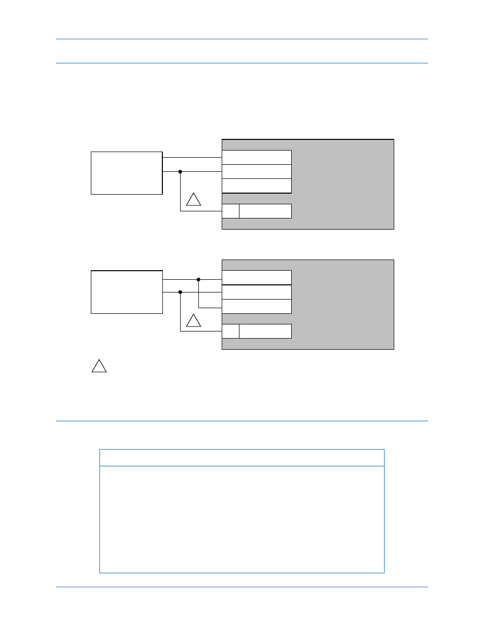
Analog Input Connections
DGC-2020HD controllers with style number xxxxxxxxR are equipped with two analog inputs and those
with style number xxxxxxxxA are equipped with four analog inputs.
Voltage and current analog input connections are shown in Figure 10. When using the current input, the
“+” and “I” terminals must be tied together.
Figure 10. Analog Engine Sender Voltage Input Connections
CAN Connections
Typical CAN connections are shown in Figure 11 and
Note
1.
If the DGC-2020HD is providing one end of the J1939 bus, a 120
Ω, ½
watt terminating resistor should be installed across terminals 51 (CAN1L)
and 52 (CAN1H) or 54 (CAN2L) and 55 (CAN2H).
2.
If the DGC-2020HD is not providing one end of the J1939 bus, the stub
connecting the DGC-2020HD to the bus should not exceed 914 mm (3 ft)
in length.
3.
The maximum bus length, not including stubs, is 40 m (131 ft).
4.
The J1939 drain (shield) should be grounded at one point only. If
grounded elsewhere, do not connect the drain to the DGC-2020HD.
ALOG IN +
ALOG IN –
ALOG IN I
DGC-2020HD
P0071-65
4 – 20 mA
Current
Transducer
BATT –
49
For optimal metering performance, it is recommended to
connect analog input common to terminal 49 (BATT –).
Note:
1
1
0 – 10 Vdc
Voltage
Transducer
ALOG IN +
ALOG IN –
ALOG IN I
DGC-2020HD
BATT –
49
1
Analog Voltage Input Connection
Analog Current Input Connection
DGC-2020HD
Typical Applications