Automatic voltage regulator (avr) control, Governor (gov) control, Load share line – Basler Electric DGC-2020HD User Manual
Page 34: Irig-b connections
24
9469300990 Rev B
parity is supported. One or two stop bits are selectable. Modbus register values for the DGC-2020HD are
listed and defined in Basler Publication 9469300991, Instruction Manual for DGC-2020HD Digital Genset
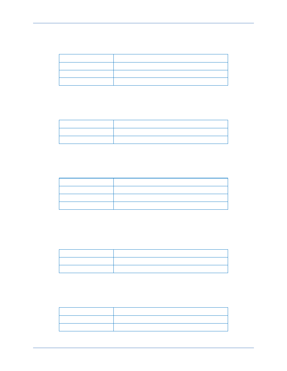
Controller Modbus™ Protocol. RS-485 interface terminals are listed in Table 14.
Table 14. RS-485 Terminals
Terminal
Description
56 (RS-485 A)
RS-485 send/receive A connection
57 (RS-485 B)
RS-485 send/receive B connection
58 (RS-485 SHIELD)
RS-485 shield connection
Automatic Voltage Regulator (AVR) Control
AVR control outputs provide control of the generator voltage setpoint. AVR control terminals are listed in
Table 15.
Table 15. AVR Control Output Terminals
Terminal
Description
64 (AVR +)
AVR control output positive
65 (AVR –)
AVR control output negative
Governor (GOV) Control
GOV control output contacts provide remote control of the generator speed (RPM) setpoint. GOV control
terminals are listed in Table 16.
Table 16. GOV Control Output Terminals
Terminal
Description
66 (GOV +)
GOV control output positive
67 (GOV –)
GOV control output negative
68 (GOV PWM)
GOV PWM output for CAT control system interface
Load Share Line
Load share line outputs are measured and used to calculate the per-unitized average load level. This
average is used as the setpoint for the genset’s kW controller. Load share line output terminals are listed
in Table 17.
Table 17. Load Share Line Output Terminals
Terminal
Description
69 (LOAD SHARE +)
Load share line positive
70 (LOAD SHARE –)
Load share line negative
IRIG-B Connections
The IRIG-B terminals connect to an IRIG-B source for synchronization of DGC-2020HD timekeeping with
the IRIG-B source. Table 18 lists the IRIG-B source input terminals.
Table 18. IRIG-B Source Input Terminals
Terminal
Description
59 (IRIG-B +)
IRIG-B source input
60 (IRIG-B –)
IRIG-B return terminal
Terminals and Connectors
DGC-2020HD