Rockwell Automation 284 ArmorStart User Manual User Manual
Page 442
F-2
24V DC Control Design Considerations
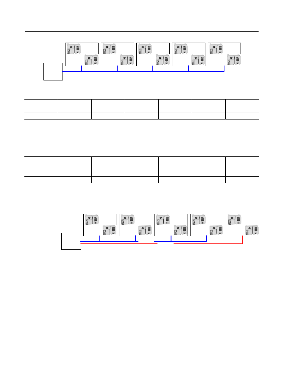
Figure F.1
Let us calculate the effective wire lengths.
Based on this calculation, there is no wire gauge that can be taken 750
feet, so the fifth section is required to have its own run.
Example 1 Re-calculated with section 5 having its own power feed
Therefore, Run 1 needs to be #10 AWG, while Run 2 can be either
#12 AWG or #10 AWG.
Figure F.2 Two-Run Wiring Solution
Example 2
Centrally locate the power supply in Example 1 – Conveyor Line
Configuration.
Conveyor
Section 1
Conveyor
Section 2
Conveyor
Section 3
Conveyor
Section 4
Conveyor
Section 5
24 vDC
Power
Supply
D1
D2
D3
D4
D5
24V DC
Power
Supply
Distance 1
Distance 2
Distance 3
Distance 4
Distance 5
Equivalent
Distance
Run 1
+ 50 ft (15 m) * 5
+ 50 ft (15 m) * 4
+ 50 ft (15 m) * 3
+ 50 ft (15 m) * 2
+ 50 ft (15 m) * 1
= 750 ft (229 m)
Distance 1
Distance 2
Distance 3
Distance 4
Distance 5
Equivalent
Distance
Run 1
+ 50 ft (15 m) * 4
+ 50 ft (15 m) * 3
+ 50 ft (15 m) * 2
+ 50 ft (15 m)
= 500 ft (152 m)
Run 2
+ 50 ft (15 m)
+ 50 ft (15 m)
+ 50 ft (15 m)
+ 50 ft (15 m)
+ 50 ft (15 m)
= 250 ft (76 m)
Conveyor
Section 1
Conveyor
Section 2
Conveyor
Section 3
Conveyor
Section 4
Conveyor
Section 5
24 vDC
Power
Supply
# 10 AWG
# 12 AWG
24V DC
Power
Supply