Rockwell Automation 284 ArmorStart User Manual User Manual
Page 323
Specifications
A-3
Bulletin 280/281, Continued
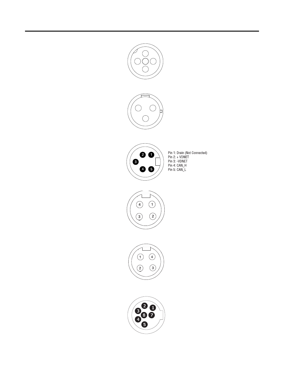
Figure A.1 External Connections for Input Connector
Figure A.2 External Connections for Output Connector
Figure A.3 External Connections for DeviceNet™ Connector
Figure A.4 External Connections for Motor Connector (
≤
3 Hp @ 460V AC)
Figure A.5 External Connections for Motor Connector (>
3 Hp @ 460V AC)
Figure A.6 External Connections for ArmorPoint Interface (IN)
Pin 1: +V Out
Pin 2: Input
Pin 3: Comm
Pin 4: Input
Pin 5: NC (No Connection)
Pin 1: PE
Pin 2: Return
Pin 3: Relay Out
Pin 1: T1 - Black
Pin 2: T2 - White
Pin 3: T3 - Red
Pin 4: Ground - Green/Yellow
Pin 1: T1 - Black
Pin 2: Ground - Green/Yellow
Pin 3: T3 - Red
Pin 4: T2 - White
Pin 1: CAN High
Pin 2: Common
Pin 3: +5V
Pin 4: CAN Low
Pin 5: Enable In
Pin 7: Common
Pin 8: PE
2
3
5
4
1
1
3
2