5motor control & motor settings – Lenze i700 User Manual
Page 94
5
Motor control & motor settings
5.9
Setting the feedback system for the servo control
94
Lenze · i700 servo inverter · Reference manual · DMS 1.5 EN · 03/2014 · TD05
_ _ _ _ _ _ _ _ _ _ _ _ _ _ _ _ _ _ _ _ _ _ _ _ _ _ _ _ _ _ _ _ _ _ _ _ _ _ _ _ _ _ _ _ _ _ _ _ _ _ _ _ _ _ _ _ _ _ _ _ _ _ _ _
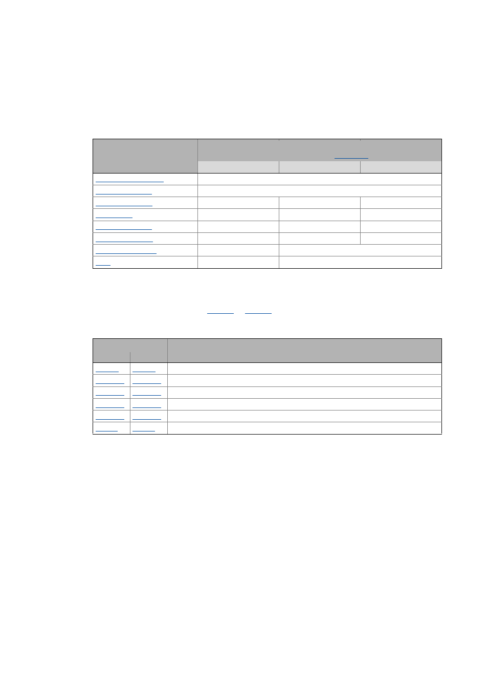
Communication error monitoring
Communication with the encoder is monitored by the protocol and by generating a checksum. If a
violation of the communication protocol or a defect frame is detected, a response occurs as a
function of the device status and the setting in subindex 4 (Hiperface communication error:
Response):
5.9.5
Detection of changed settings of the feedback system
Bit 0 of the Lenze statusword 2 (
or
for axis B) indicates whether the settings of the
feedback system have been changed during operation. Bit 0 is set to"1" if one of the following
objects have been changed since the last controller inhibit:
After a controller enable, bit 0 of the Lenze status word 2 is always reset to "0".
Device status
Response in the event of an error
(depending on the error responses set in the
0: No Response
1: Trouble
2: Warning
Warning
Warning
-
Fault
Warning
-
Fault
Warning
-
Fault
Warning
-
Fault
Warning
-
Warning
-
Warning
Object
Name
Axis A
Axis B
Encoder: Type
Hiperface: User defined - Type code
Hiperface: User defined - Number of revolutions
Hiperface: Serial number
Encoder: Increments / revolution
Position encoder resolution