7 setting the oscillation damping, Setting the oscillation damping, 5motor control & motor settings – Lenze i700 User Manual
Page 146
5
Motor control & motor settings
5.14
Parameterising the V/f characteristic control
146
Lenze · i700 servo inverter · Reference manual · DMS 1.5 EN · 03/2014 · TD05
_ _ _ _ _ _ _ _ _ _ _ _ _ _ _ _ _ _ _ _ _ _ _ _ _ _ _ _ _ _ _ _ _ _ _ _ _ _ _ _ _ _ _ _ _ _ _ _ _ _ _ _ _ _ _ _ _ _ _ _ _ _ _ _
5.14.7
Setting the oscillation damping
The oscillation damping serves to reduce the oscillations during no-load operation which are caused
by energy oscillating between the mechanical system (mass inertia) and the electrical system (DC
bus). Furthermore, the oscillation damping can also be used to compensate resonances.
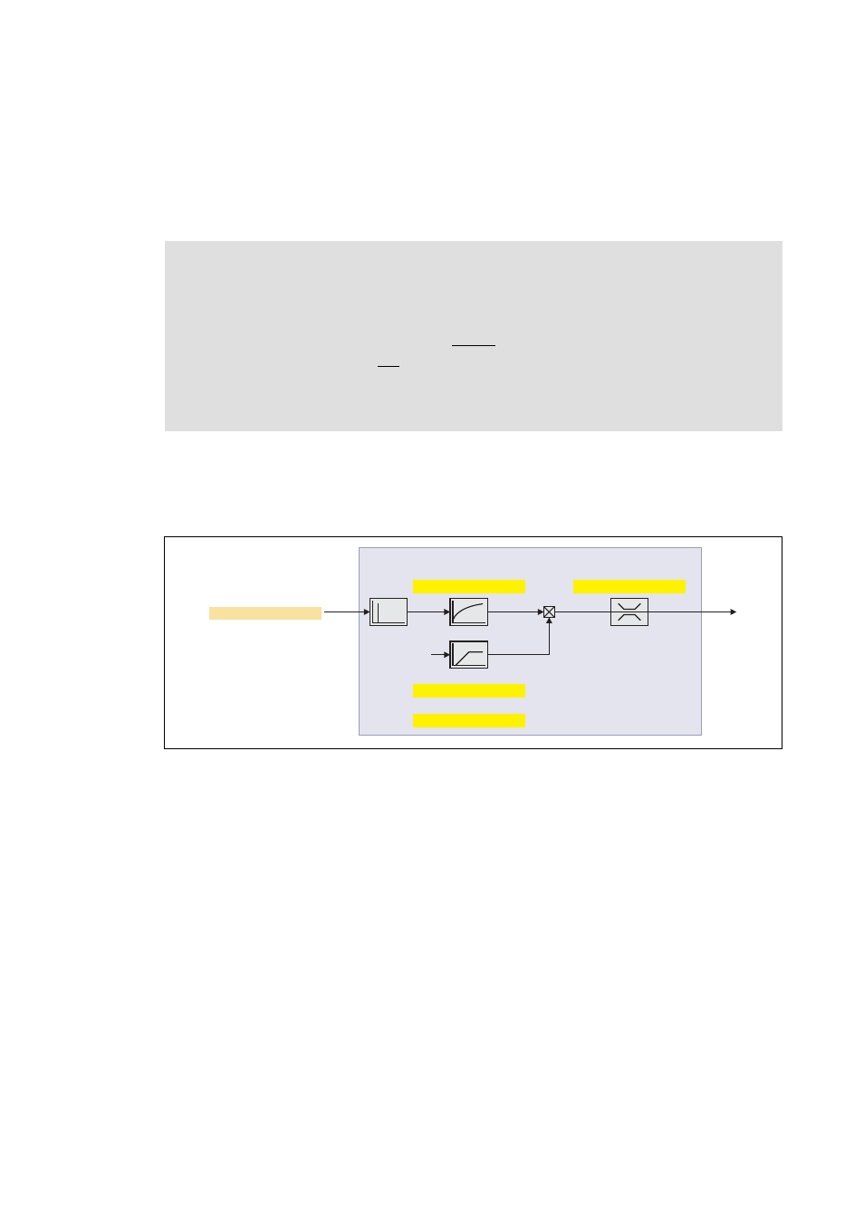
Function
The determination of the oscillation is based on the active current. In order to obtain the alternating
component of the active current, this current is differentiated. This signal is then passed through a
PT1 filter.
Identification of the oscillation
Before the oscillation damping can be parameterised, the oscillation has to be identified. One way
to do this is to examine the motor current while oscillation damping is switched off (gain = 0 %). At
steady-state operation, a constant current flows. If the drive oscillates, these oscillations are also
visible on the motor current. It is therefore possible to determine the frequency and the amplitude
of the oscillation from the alternating component of the motor current. In the following, this
alternating component is referred to as "current oscillation".
Note!
Observe the following restrictions:
• Damping is possible only for constant oscillations at a steady-state operating point.
• Oscillations occurring sporadically cannot be damped.
• Oscillation damping is not suitable for oscillations occurring during dynamic
processes (e.g. accelerations or load changes).
• Oscillation damping is only active if the setpoint speed is greater than 10 rpm and the
DC-bus voltage exceeds a value of 100 V.
0x2DD1:2 | 0x35D1:2
0x2B0A:2 | 0x330A:2
0x2B0A:1 | 0x330A:1
0x2B0A:4 | 0x330A:4
0x2B0A:3 | 0x330A:3
Q-current (iq): Actual current
Filter time
Gain
Ramp-end frequency
Limitation
Set value
mot. frequency
Oscillation damping