Setting the feedback system for the servo control, 5motor control & motor settings – Lenze i700 User Manual
Page 85
Lenze · i700 servo inverter · Reference manual · DMS 1.5 EN · 03/2014 · TD05
85
5
Motor control & motor settings
5.9
Setting the feedback system for the servo control
_ _ _ _ _ _ _ _ _ _ _ _ _ _ _ _ _ _ _ _ _ _ _ _ _ _ _ _ _ _ _ _ _ _ _ _ _ _ _ _ _ _ _ _ _ _ _ _ _ _ _ _ _ _ _ _ _ _ _ _ _ _ _ _
5.9
Setting the feedback system for the servo control
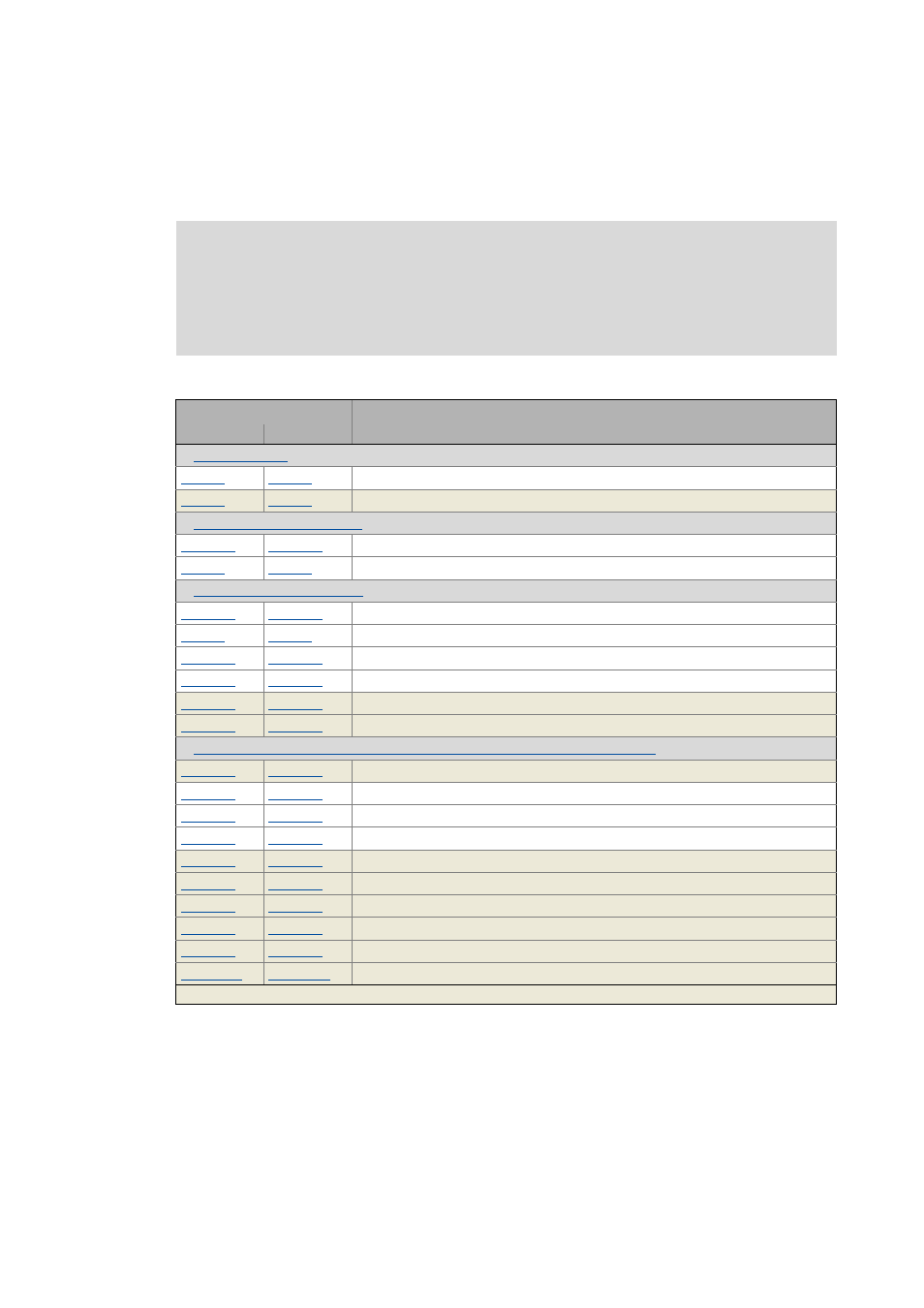
After setting the motor parameters, the feedback system for the servo control must be set.
The following table shows which parameters are valid for which feedback system:
Note!
The feedback system has already been preselected by the hardware of the available
device version. Either the objects for resolver evaluation or the objects for encoder
evaluation are effective. Access to ineffective objects of hardware not available is
ignored.
Object
Name
Axis A
Axis B
Open circuit in feedback system: Response
Feedback system: Specifiable number of revolutions
Settings for "resolver" version
Motor (SM): Pole position resolver
Resolver: Number of pole pairs
Settings for "encoder" version
Motor (SM): Pole position encoder
Encoder: Type
Encoder: Increments / revolution
Encoder: Supply voltage
Encoder: Angle drift - Actual angle error
Encoder: Signal quality - Actual amplitude
Additional settings for SinCos absolute value encoders with HIPERFACE® protocol
Hiperface: Determined type code
Hiperface: User def. encoder - type code
Hiperface: User def. encoder - specifiable revolutions
Hiperface absolute value fault: Response
Hiperface: Serial number
Hiperface: Raw data - Actual position
Hiperface: Detected Increments / revolution
Hiperface: Type code supported by firmware
Hiperface: Encoder type
Hiperface: Period length linear encoder
Greyed out = read access only