5motor control & motor settings – Lenze i700 User Manual
Page 79
Lenze · i700 servo inverter · Reference manual · DMS 1.5 EN · 03/2014 · TD05
79
5
Motor control & motor settings
5.8
Setting the motor parameters for the servo control
_ _ _ _ _ _ _ _ _ _ _ _ _ _ _ _ _ _ _ _ _ _ _ _ _ _ _ _ _ _ _ _ _ _ _ _ _ _ _ _ _ _ _ _ _ _ _ _ _ _ _ _ _ _ _ _ _ _ _ _ _ _ _ _
After the parameters have been extracted from the impedance, they are checked for consistency
with the required rated values. If an inconsistent parameter set is detected, is this an indication of
faulty rated values on the nameplate.
Preconditions for the execution
• The synchronous motor must be able to rotate freely.
• The asynchronous motor may be firmly braked.
• The controller is free of errors and is in the "
" device status.
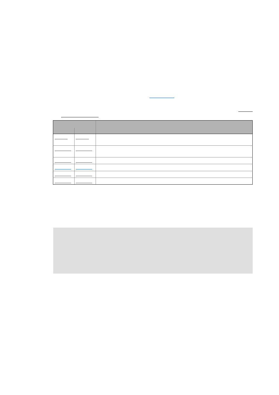
• The motor parameters listed in the following table are excluded from the automatic
determination and must therefore be adapted to the motor used (see motor nameplate before
the determination.
Response of the motor during the execution
• A DC current is superimposed over the identification current that keeps the motor idling. After
the controller enable, the shaft will adjust once, which is irrelevant to measurement though.
• With asynchronous motors, slight rotations might possibly occur. Their influence on the
measurements is, however, not worth mentioning.
Object
Name
Axis A
Axis B
Motor rated current
(The current amount for the procedure is derived from this specification)
Motor: Stator resistance
(Default setting is used as starting value for the automatic determination.)
Motor: Rated speed
Motor: Rated frequency
Motor: Rated power
Motor: Rated voltage
Note!
• In case of uncertainties, the measurement should be repeated several times to check
if the results for the stator resistance, the leakage inductance of the stator and the
rotor resistance differ widely. This should not be the case.
• The mutual inductance and the cos(ϕ) values are not that important for the
diagnostics, because they are strongly non-linear.