4 monitoring of the motor utilisation (i·xt), Monitoring of the motor utilisation (i²xt), 0x2d4e – Lenze i700 User Manual
Page 241: 0x354e, 0x2d4f, 0x354f, 8monitoring functions, Stop
Lenze · i700 servo inverter · Reference manual · DMS 1.5 EN · 03/2014 · TD05
241
8
Monitoring functions
8.4
Monitoring of the motor utilisation (I²xt)
_ _ _ _ _ _ _ _ _ _ _ _ _ _ _ _ _ _ _ _ _ _ _ _ _ _ _ _ _ _ _ _ _ _ _ _ _ _ _ _ _ _ _ _ _ _ _ _ _ _ _ _ _ _ _ _ _ _ _ _ _ _ _ _
8.4
Monitoring of the motor utilisation (I²xt)
This monitoring detects the thermal utilisation of the motor by calculating the thermal motor
utilisation from the detected motor currents based on a mathematical model and displaying it in
the object
for axis B).
In case of permanent overload and excess of the warning threshold set in the object
(or
for axis B), a warning is output in order that the higher-level Controller is still able to
respond and reduce the motor load or interrupt the operation.
From version 01.04 on
, an error response in the object
for axis B) can be
parameterised as well if the disconnection should not or cannot be executed by a higher-level
Controller.
During the calculation, the speed dependence of the permissible motor load and thus of the
permissible current (difference between the standstill current and rated current is taken into
consideration. This is done via object
for axis B).
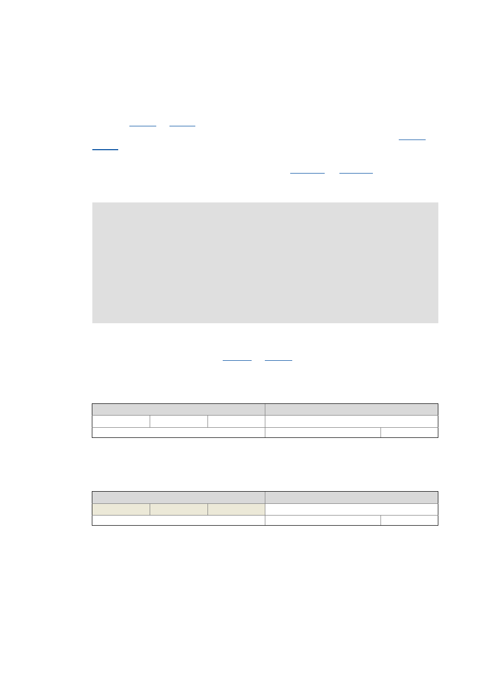
The threshold value for the warning output can be adapted via the following object:
0x2D4E | 0x354E - Motor utilisation (I²xt): Motor overload warning threshold
The current thermal motor utilisation is shown in the following object:
0x2D4F | 0x354F - Motor utilisation (I²xt): Actual utilisation
Stop!
Monitoring the motor utilisation (I²xt) is not a means for full motor protection!
Since the motor utilisation calculated in the thermal model gets lost after mains
switching, the following operating states cannot be determined correctly:
• Restarting (after mains switching) of a motor that is already very hot.
• Change of the cooling conditions (e.g. cooling air flow interrupted or too warm).
Full motor protection requires additional measures such as the evaluation of
temperature sensors that are located directly in the winding or the use of thermal
contacts.
Setting range
(min. value | unit | max. value)
Lenze setting
0
%
250 100 %
Write access CINH OSC P RX TX
UNSIGNED_16
Display area
(min. value | unit | max. value)
Initialisation
0
%
250
Write access CINH OSC P RX TX
UNSIGNED_16