4 structure of the parameter descriptions, Structure of the parameter descriptions, 1about this documentation – Lenze i700 User Manual
Page 16
1
About this documentation
1.4
Structure of the parameter descriptions
16
Lenze · i700 servo inverter · Reference manual · DMS 1.5 EN · 03/2014 · TD05
_ _ _ _ _ _ _ _ _ _ _ _ _ _ _ _ _ _ _ _ _ _ _ _ _ _ _ _ _ _ _ _ _ _ _ _ _ _ _ _ _ _ _ _ _ _ _ _ _ _ _ _ _ _ _ _ _ _ _ _ _ _ _ _
1.4
Structure of the parameter descriptions
All parameters which you can use to parameterise or monitor the i700 servo inverter are stored
within "objects".
• For the purpose of addressing, each object is provided with a unique index. In this
documentation the index is represented as a hexadecimal value and is identified by a prefixed
"0x", e.g. "0x1000".
• If an object contains several parameters, they are stored in "subindexes". In this documentation
the colon is used as a separator between the index and the subindex, e.g. "0x1018:1".
Each parameter description is structured according to the following pattern:
Note!
This documentation is valid for the i700 servo inverter in the single axis version (single
inverter) and also as double axis (double inverter).
For parameters referring to one axis, both indexes (for axis A and axis B) are listed in the
parameter description. For a single axis, only the first index is relevant in this case.
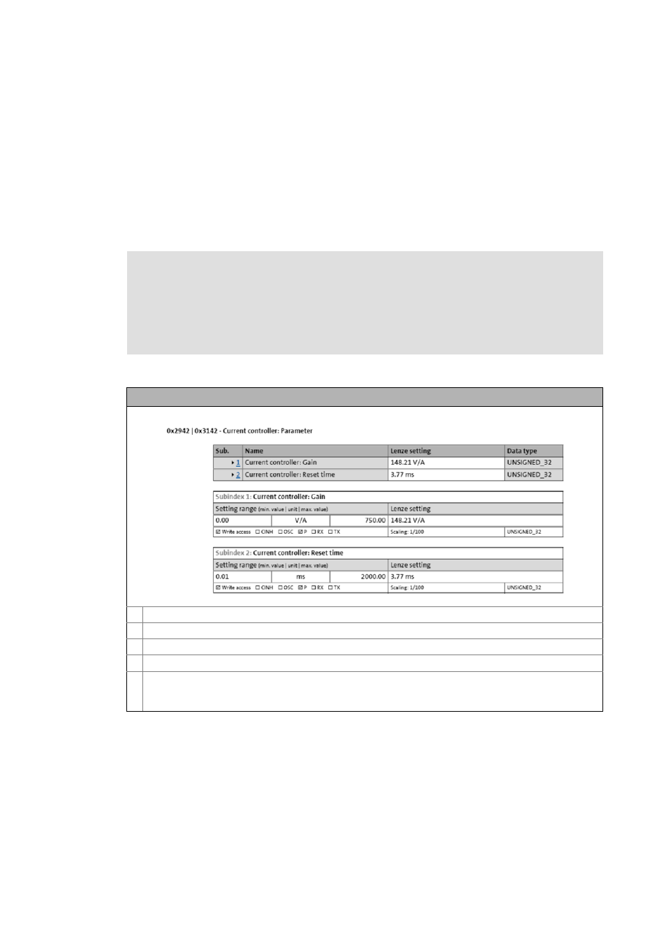
Example: Structure of the parameter descriptions in this documentation
Object index for axis A
Object index for axis B (only relevant for double axis)
Parameter or object name
If the object contains several parameters: Overview table with list of all subindexes
Table with detailed information about the corresponding parameter:
• Explanations & references (optional)
• Display options/possible settings, Lenze setting, attributes (for the meaning see the following table)