5motor control & motor settings – Lenze i700 User Manual
Page 110
5
Motor control & motor settings
5.11
Setting control loops
110
Lenze · i700 servo inverter · Reference manual · DMS 1.5 EN · 03/2014 · TD05
_ _ _ _ _ _ _ _ _ _ _ _ _ _ _ _ _ _ _ _ _ _ _ _ _ _ _ _ _ _ _ _ _ _ _ _ _ _ _ _ _ _ _ _ _ _ _ _ _ _ _ _ _ _ _ _ _ _ _ _ _ _ _ _
6. Record the step response of the motor current with the oscilloscope function of the »PLC
Designer«/»EASY Starter«.
• Parameters to be recorded:
Actual D current (
or
for axis B)
Setpoint D current (
or
for axis B)
D voltage (
or
for axis B)
• Oscilloscope settings: Sampling rate = 0.0625 ms; time base = 2 ... 5 ms
Alternatively, the step response of the motor current in the motor phase U can be
measured by means of an oscilloscope and clamp-on ammeter.
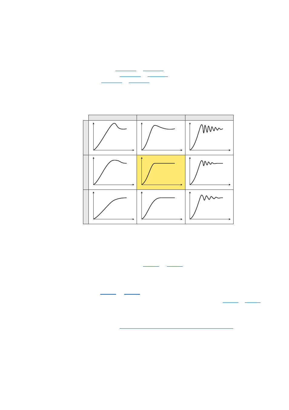
7. Evaluate the step response:
8. Adjust the gain and reset time of the current controller.
9. Repeat steps 3 ... 6 iteratively until the optimum step response of the motor current is
reached.
• In the optimised state the current rise time typically is 0.5 ... 1 ms.
• If the adjustment does not provide any satisfactory results, the current controller
feedforward control via object
(or
for axis B) can be activated
additionally. Then steps 3 ... 6 are to be repeated.
10. To stop the test mode:
• Inhibit controller.
• Set object
(or
for axis B) to "0" to change back to the CiA402 mode.
11. For permanent storage: Upload changed current controller parameters (
or
for axis B) from the i700 servo inverter into the Controller.
The »EASY Starter« serves to save the parameter settings of the i700 servo inverter as
parameter file (*.gdc). In the »PLC Designer«, this file can then be imported in the
corresponding axis.
Saving changed parameters safe against mains failure
I
t
I
t
I
t
I
t
I
t
I
t
I
t
I
t
I
t
Vp < Vp opt.
Vp = Vp opt.
Vp > Vp opt.
Tn
<
T
n
opt.
Tn
=
T
n
opt.
Tn
>
T
n
opt.