6holding brake control – Lenze i700 User Manual
Page 162
6
Holding brake control
6.4
Settings
162
Lenze · i700 servo inverter · Reference manual · DMS 1.5 EN · 03/2014 · TD05
_ _ _ _ _ _ _ _ _ _ _ _ _ _ _ _ _ _ _ _ _ _ _ _ _ _ _ _ _ _ _ _ _ _ _ _ _ _ _ _ _ _ _ _ _ _ _ _ _ _ _ _ _ _ _ _ _ _ _ _ _ _ _ _
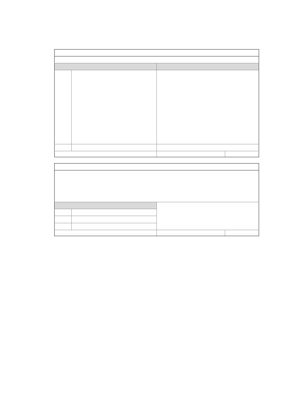
Subindex 5:
Brake: Control logic
The control logic of the holding brake can be inverted.
Selection list
(Lenze setting printed in bold)
Info
0 Positive logic
Positive logic means:
• Release of the holding brake: The 1-signal serves to
trigger the brake output via bit 14 in the CiA402
control word or by the device state machine (relay
contact closed).
• In the CiA402 status word, bit 14 is set (holding brake
released).
Negative logic means:
• Level inversion of the relay output.
• Release of the holding brake: The 1-signal does not
trigger the brake output via bit 14 in the CiA402
control word or by the device state machine (relay
contact is open).
• In the CiA402 status word, bit 14 is set (holding brake
released).
1 Negative logic
Write access CINH OSC P RX TX
UNSIGNED_8
Subindex 6:
Brake monitoring: Response
In the controlled state, the holding brake is monitored cyclically for the presence of the brake current.
Since, after connecting the holding brake, the brake current builds up in a time-delayed manner as a function of
inductance, an open circuit, a terminal short circuit, or a missing brake supply is detected with a delay.
When monitoring trips, the response set here will be activated.
Note:
The holding brake is not monitored in the non-triggered state!
Selection list
(Lenze setting printed in bold)
0 No response
1 Fault
2 Warning
Write access CINH OSC P RX TX
UNSIGNED_8