3 ready to switch on, Ready to switch on, To the – Lenze i700 User Manual
Page 183: Devi, 7cia402 device profile
Lenze · i700 servo inverter · Reference manual · DMS 1.5 EN · 03/2014 · TD05
183
7
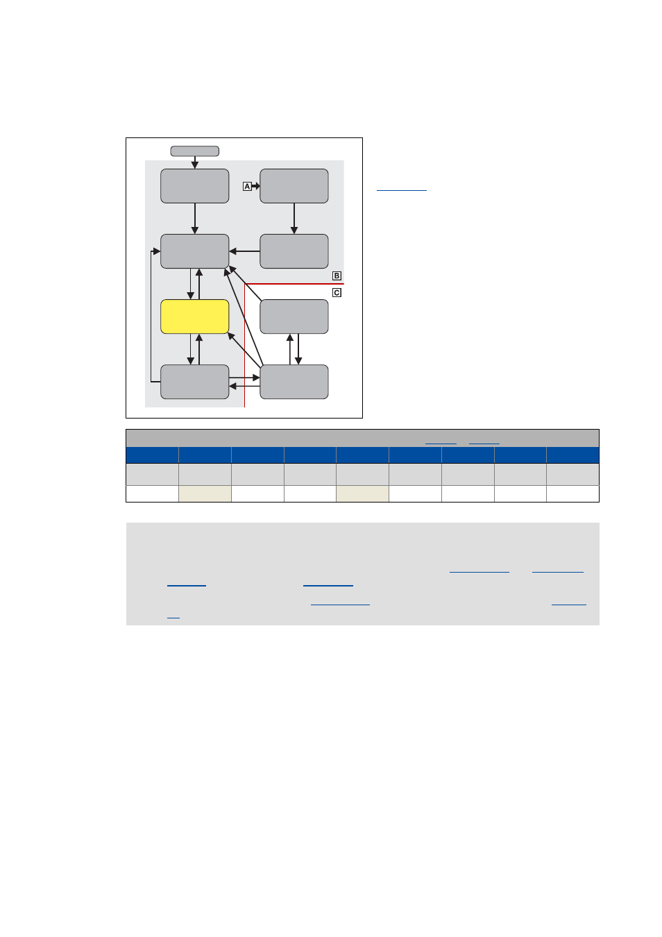
CiA402 device profile
7.4
Device control
_ _ _ _ _ _ _ _ _ _ _ _ _ _ _ _ _ _ _ _ _ _ _ _ _ _ _ _ _ _ _ _ _ _ _ _ _ _ _ _ _ _ _ _ _ _ _ _ _ _ _ _ _ _ _ _ _ _ _ _ _ _ _ _
7.4.2.3
Ready to switch on
This is the device status of the controller after
the device has been initialised successfully and
after the controller has received the
"
• The process data monitoring is active.
• Communication is possible.
• DC-bus voltage is available.
• The inverter can be parameterised.
• The motor brake, if available, is closed.
• The operation is inhibited.
Bit pattern for the "Ready to switch on" device status in the Statusword (
for axis B):
Bits 15 - 8
Bit 7
Bit 6
Bit 5
Bit 4
Bit 3
Bit 2
Bit 1
Bit 0
Warning is
active
Switch on
disabled
Quick stop
Voltage
enabled
Fault active
Operation
enabled
Switched on
Ready to
switch on
X
X
0
1
X
0
0
0
1
Note!
A changeover to this device status is also effected if, in the
" command is activated.
The change to the sequential "
" state is effected by activation of the "
Ready to
switch on
Not ready to
switch on
Switched
on
Operation
enabled
Fault reaction
active
Fault
active
Switch on
disabled
Quick stop
active
Power on