1 led status displays, Led status displays, 9diagnostics & error management – Lenze i700 User Manual
Page 260
9
Diagnostics & error management
9.1
LED status displays
260
Lenze · i700 servo inverter · Reference manual · DMS 1.5 EN · 03/2014 · TD05
_ _ _ _ _ _ _ _ _ _ _ _ _ _ _ _ _ _ _ _ _ _ _ _ _ _ _ _ _ _ _ _ _ _ _ _ _ _ _ _ _ _ _ _ _ _ _ _ _ _ _ _ _ _ _ _ _ _ _ _ _ _ _ _
9.1
LED status displays
The LED status displays on the front of the i700 servo inverter provide quick information on some
operating states.
• The two LEDs "RDY" and "ERR" serve to indicate the device status.
• Three green LEDs at the EtherCAT interfaces (RJ45 sockets X4 and X5) serve to indicate the
EtherCAT bus status and the connection status of the input and output socket. The arrangement
of the LEDs can be seen from the "Servo-Inverter i700" hardware manual.
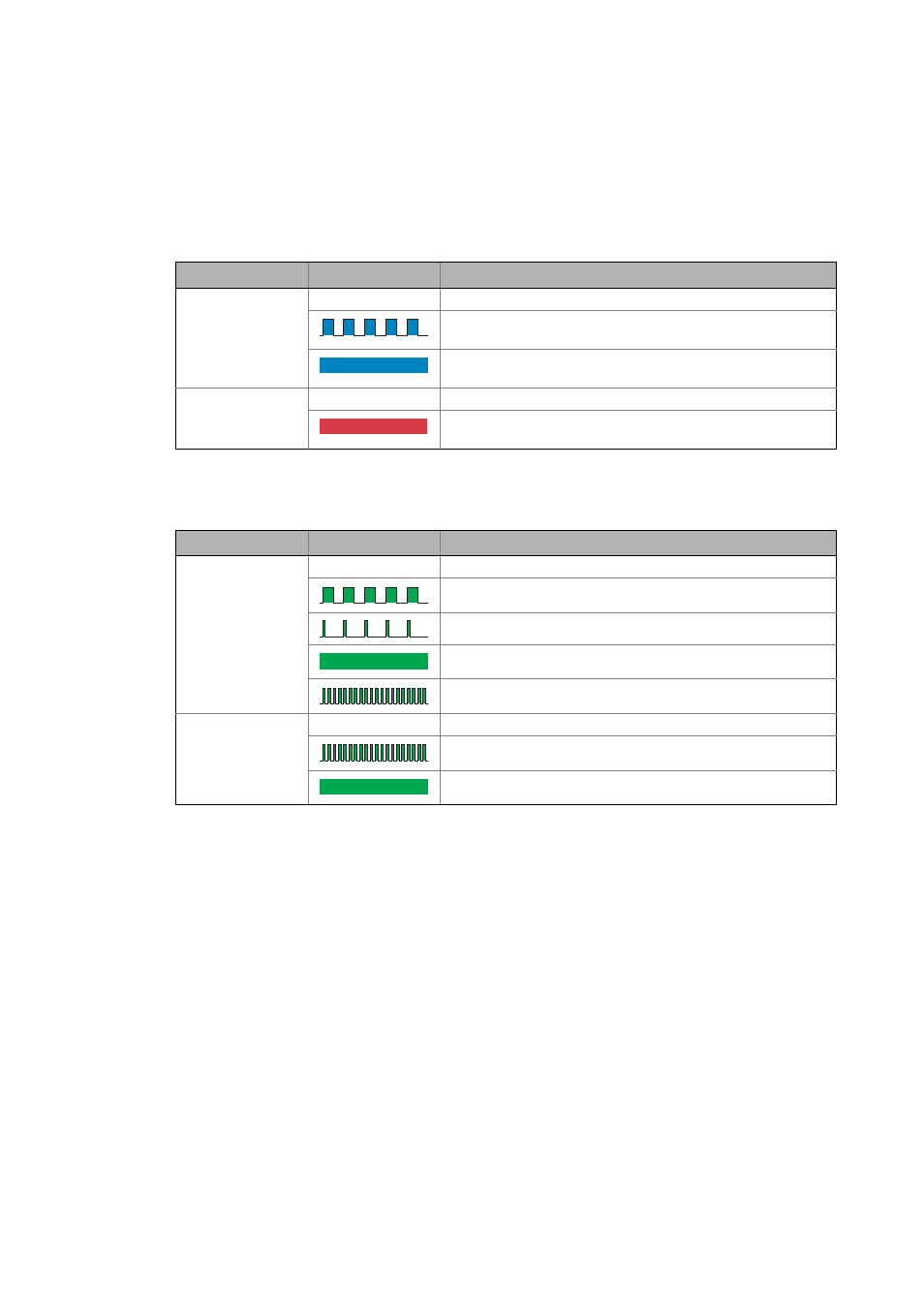
LED
Status
Meaning
RDY
Off
24 V supply voltage missing
Single axis: Axis is inhibited
Double axis: Both axes are inhibited
Single axis: Axis is enabled
Double axis: One or both axes are enabled
ERR
Off
No error.
Single axis: Device error or axis error
Double axis: Device error or axis error in one axis or both axes
LED
Status
Meaning
RUN
Off
EtherCAT status "Init"
EtherCAT state "Pre-Operational"
EtherCAT state "Safe-Operational"
EtherCAT state "Operational"
EtherCAT state "Bootstrap"
L/A
Off
No EtherCAT connection
EtherCAT communication active
EtherCAT connection available