3 enable operation, Enable operation, 7cia402 device profile – Lenze i700 User Manual
Page 174
7
CiA402 device profile
7.4
Device control
174
Lenze · i700 servo inverter · Reference manual · DMS 1.5 EN · 03/2014 · TD05
_ _ _ _ _ _ _ _ _ _ _ _ _ _ _ _ _ _ _ _ _ _ _ _ _ _ _ _ _ _ _ _ _ _ _ _ _ _ _ _ _ _ _ _ _ _ _ _ _ _ _ _ _ _ _ _ _ _ _ _ _ _ _ _
7.4.1.3
Enable operation
From all states
Power section inhibited (pulse inhibit)
Power section enabled
This command serves to enable the operation
and stop an active quick stop again.
• A changeover to the "
device status takes place.
• The output stages of the controller become
active.
Bit pattern for the "Enable operation" command in the Controlword (
for axis B):
Bits 15 - 8
Bit 7
Bit 6
Bit 5
Bit 4
Bit 3
Bit 2
Bit 1
Bit 0
Fault reset
Control bits depending on the operating mode
Enable
operation
Activate quick
stop
Enable voltage
Switch on
X
0
X
X
X
1
1
1
1
Note!
The signalling of the "
" device status in the CiA402 status word can be
delayed in the following cases:
• If in case of the synchronous motor servo control the "pole position identification
option has been activated before the start in
for axis B) and is just
running (few milliseconds).
• If the brake is in the "control via device state machine" mode and the brake opening
time (
for axis B) has not elapsed yet.
• If an asynchronous motor is used which has not been magnetised yet.
Check the setting of the rated motor current (
maximum device current (
" device status is signalled in the CiA402 status word,
the points mentioned before are concluded and the i700 servo inverter is ready for the
acceptance of setpoints of the Controller.
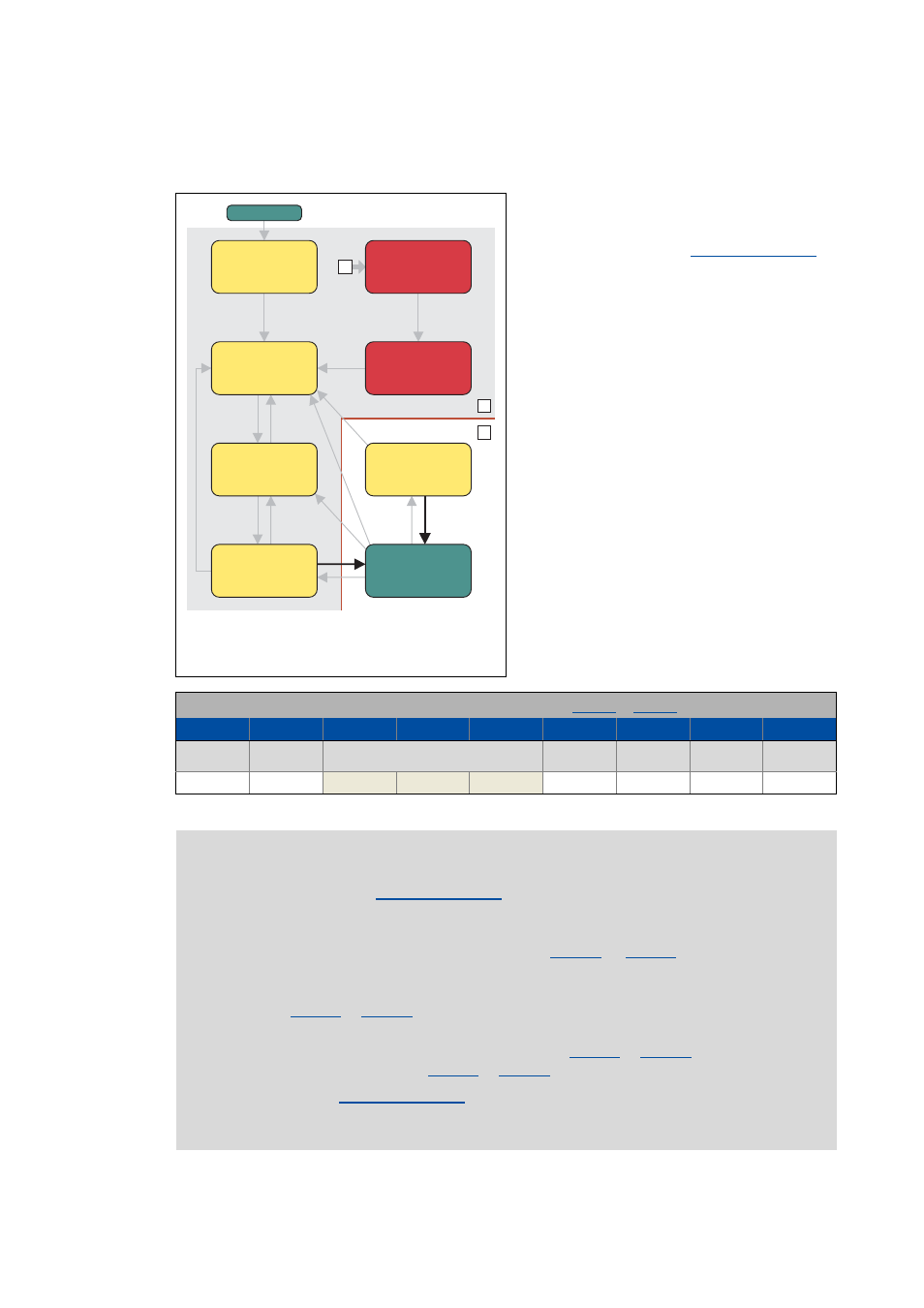
1
2
0
Power on
Ready to
switch on
Not ready to
switch on
Switched
on
Operation
enabled
Fault reaction
active
Fault
Switch-on
disabled
Quick stop
active
Power-on