1 jerk limitation, 0x2945 | 0x3145 - torque: setpoint jerk limitation, 2 notch filters (band-stop filters) – Lenze i700 User Manual
Page 132: Jerk limitation, Notch filters (band-stop filters), 0x2945, 0x3145, 5motor control & motor settings, Stop
5
Motor control & motor settings
5.13
Parameterising filter elements in the setpoint path
132
Lenze · i700 servo inverter · Reference manual · DMS 1.5 EN · 03/2014 · TD05
_ _ _ _ _ _ _ _ _ _ _ _ _ _ _ _ _ _ _ _ _ _ _ _ _ _ _ _ _ _ _ _ _ _ _ _ _ _ _ _ _ _ _ _ _ _ _ _ _ _ _ _ _ _ _ _ _ _ _ _ _ _ _ _
5.13
Parameterising filter elements in the setpoint path
5.13.1
Jerk limitation
Max. acceleration change
0x2945 | 0x3145 - Torque: Setpoint jerk limitation
5.13.2
Notch filters (band-stop filters)
Due to the high dynamic performance or the high limit frequency of the closed current control loop,
mechanical natural frequencies can be excited, which can result in resonance and thus cause the
speed control loop to become unstable.
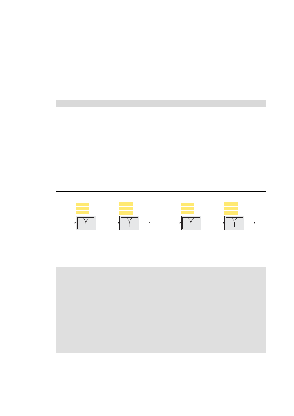
In order to suppress or damp these resonant frequencies, two notch filters are integrated in the
speed control loop of the controller, which can be parameterised. In the Lenze setting, these filters
are switched off:
[5-7]
Optional notch filters (filter cascade) in the speed control loop
Use of the notch filters depending on the resonant frequency
Setting range
(min. value | unit | max. value)
Lenze setting
0.1
%
400.0 400.0 %
Write access CINH OSC P RX TX
Scaling: 1/10
UNSIGNED_16
Axis A
Axis B
m = Output of the jerk limitation
0x2944:3
0x2944:2
0x2944:1
Filter 1
0x2944:6
0x2944:5
0x2944:4
Filter 2
m
m*
Frequency [Hz]
Width [Hz]
Depth [dB]
Frequency [Hz]
Width [Hz]
Depth [dB]
0x3144:3
0x3144:2
0x3144:1
Filter 1
0x3144:6
0x3144:5
0x3144:4
Filter 2
m
m*
Frequency [Hz]
Width [Hz]
Depth [dB]
Frequency [Hz]
Width [Hz]
Depth [dB]
Stop!
If the filter parameters are set incorrectly, the impaired closed-loop control can respond
with too large overshoots and cause the controller to become unstable, e.g. if the filter
width is set to a value more than twice as large as the filter frequency.
After setting the filter parameters, the drive behaviour for quick stop (QSP) must be
checked.
In the case of impairment,
• the drive that is still running must either be coasted down by activating the controller
inhibit or immediately be brought to a standstill via a brake.
• the speed controller must be optimised again afterwards.
• the test procedure must be repeated.