2 device states, Device states, Device – Lenze i700 User Manual
Page 179: States, 7cia402 device profile
Lenze · i700 servo inverter · Reference manual · DMS 1.5 EN · 03/2014 · TD05
179
7
CiA402 device profile
7.4
Device control
_ _ _ _ _ _ _ _ _ _ _ _ _ _ _ _ _ _ _ _ _ _ _ _ _ _ _ _ _ _ _ _ _ _ _ _ _ _ _ _ _ _ _ _ _ _ _ _ _ _ _ _ _ _ _ _ _ _ _ _ _ _ _ _
7.4.2
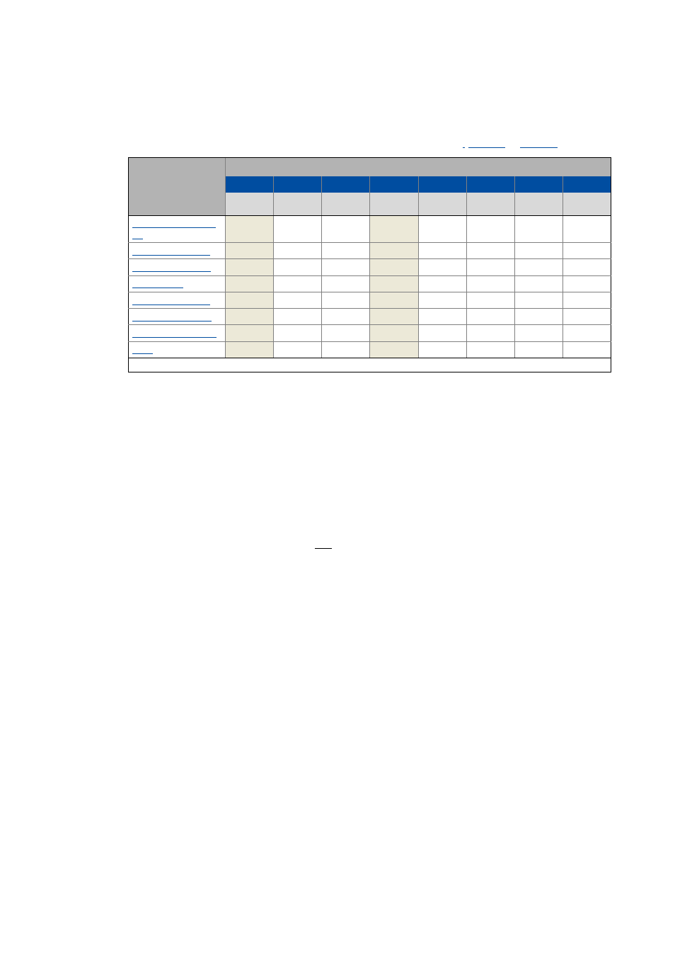
Device states
The current device status of the drive can be read via the Statusword
(
for axis B):
Tip!
Bits 4 ("Voltage enabled") and 7 ("Warning active") are not relevant as regards the device
status and merely serve the purpose of a better readability of the bit patterns here.
Detailed information on the different device states can be obtained from the following
subchapters.
"Warning active" status bit
Via bit 7 in the Statusword, a warning is indicated.
• The occurrence of a warning does not cause a state change.
• Warnings do not need to be reset.
Device status
Bit pattern in the Statusword
Bit 7
Bit 6
Bit 5
Bit 4
Bit 3
Bit 2
Bit 1
Bit 0
Warning is
active
Switch on
disabled
Quick stop
Voltage
enabled
Fault active
Operation
enabled
Switched on
Ready to
switch on
X
0
X
X
0
0
0
0
X
1
X
X
0
0
0
0
X
0
1
X
0
0
0
1
X
0
1
X
0
0
1
1
X
0
1
X
0
1
1
1
X
0
0
X
0
1
1
1
X
0
X
X
1
1
1
1
X
0
X
X
1
0
0
0
X = Status not significant