24 e-shaft: speed-dependent angular trimming, 24 e−shaft: speed−dependent angular trimming, Commissioning – Lenze ECSCPxxx User Manual
Page 235
Commissioning
E−Shaft: Speed−dependent angular trimming
l
235
EDBCSXP064 EN 8.0
6.24
E−Shaft: Speed−dependent angular trimming
Application
The transmission of the master angle from the digital frequency master to the slave drives
causes an offset over time (dead time) between master and slave drives. With increasing
speed, this dead time causes an increasing angular offset of the slaves compared to the
master.
When the electrical shaft is used, the angular offset in the slave can be compensated via
the "Speed−proportional angular trimming" function. This function is only active in the
positioning profile mode "Electrical shaft" (C3095 = 30, 31, 32)!
p
n
f
0
p
n
f
0
-
+
f
n_trim
f
n_trim
Master
(z. B. Leitgeber)
Slave
(Antrieb)
ECSXA455
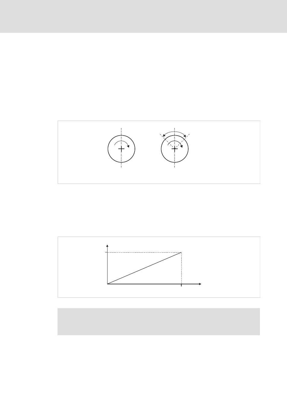
Fig. 6−59
Angular trimming in the slave drive
In the slave drives, the effective angular trimming is calculated based on the angular
trimming characteristic as a function of the master speed (linear characteristic).
The user can adapt the slope of this linear characteristic by entering a point on the
characteristic. Under code C4060, the required angular offset for the master speed of
15000 rpm is entered. The entry is done in increments, and 2
16
increments correspond to
one revolution of the motor shaft.
f
n_trim
n_set
15000 rpm
C4060
ECSXA456
Fig. 6−60
Linear connection in the speed−proportional angular trimming
)
Note!
The value C4060 is only to be changed at standstill of the drive to prevent
speed steps.
The value of angular trimming becoming effective at the current speed is displayed in
C4061.
The codes C4060 and C4061 can be found in the GDC parameter menu under
Positioning/E−shaft
W E−shaft − slave.