14 configuring the digital inputs and outputs – Lenze ECSCPxxx User Manual
Page 168
Commissioning
Configuring the digital inputs and outputs
l
168
EDBCSXP064 EN 8.0
6.14
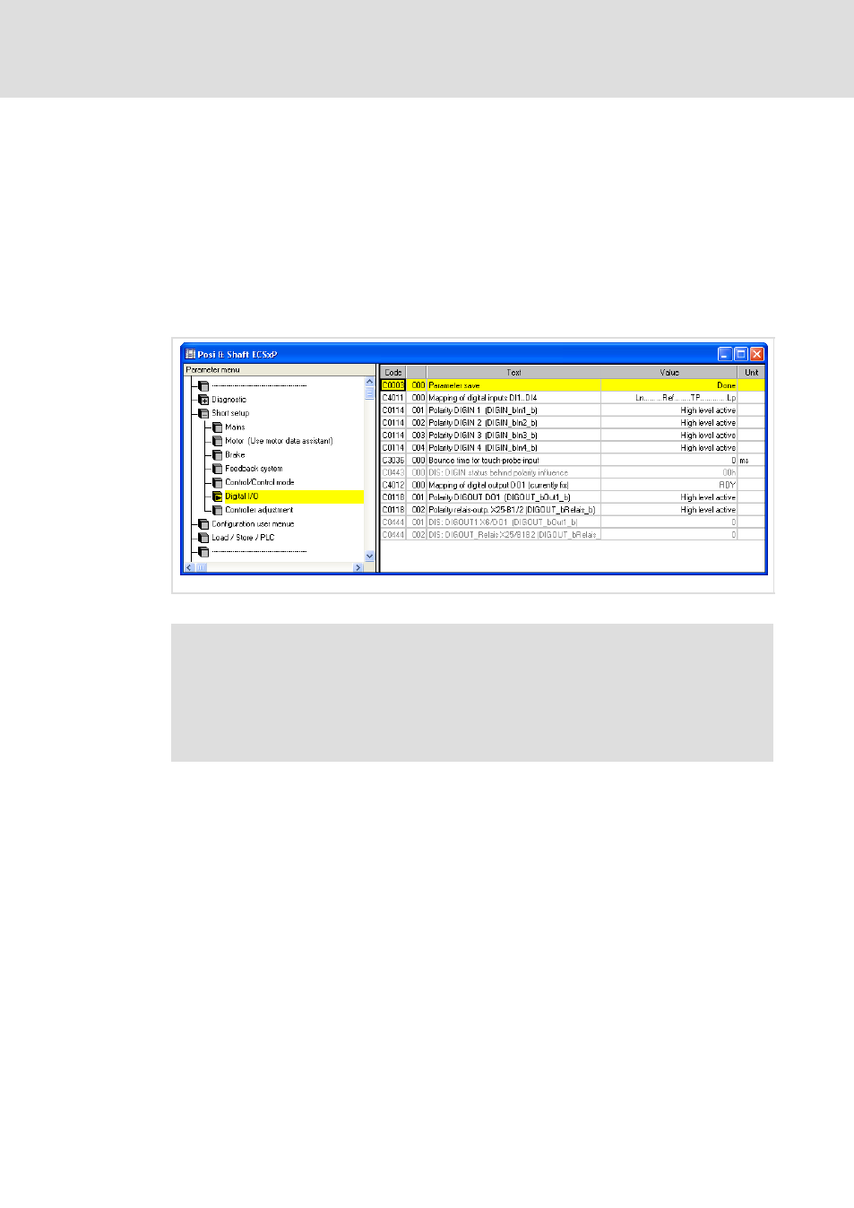
Configuring the digital inputs and outputs
In the GDC parameter menu under Short setup
W Digital inputs/outputs you’ll find the
codes for setting the signal assignment of the digital inputs X6/DI1 ... DI4 (C4011) and the
digital output X6/DO1 (C4012).
ƒ
The digital inputs X6/DI1 ... DI4 and the control bits of the control word Ctrl1 have
the same priority. Both signals are OR’d. If a digital input or the corresponding bit is
set in the control word, the control signal is transmitted as set to the drive.
ƒ
The RDY signal (ready for operation) is fixedly assigned to the digital output X6/DO1.
ECSXA454
Fig. 6−28
GDC view: Codes for configuring the digital inputs and outputs
)
Note!
When using fail−safe limit switches (NC contacts), set the polarity of the digital
inputs with C0114/x = 1 (LOW level active).
The OR operation of the digital inputs and control bits is implemented as of
Posi & Shaft V2.0 (A−SW). Up to Posi & Shaft V1.x, the digital inputs had
priority over the control bits.