Commissioning, Ecsxp customer plc, Fig. 6−14 structure of ecs "posi and shaft – Lenze ECSCPxxx User Manual
Page 108
Commissioning
Basic terms of positioning
Device structure and interfaces to the higher−level control
l
108
EDBCSXP064 EN 8.0
6.1.12
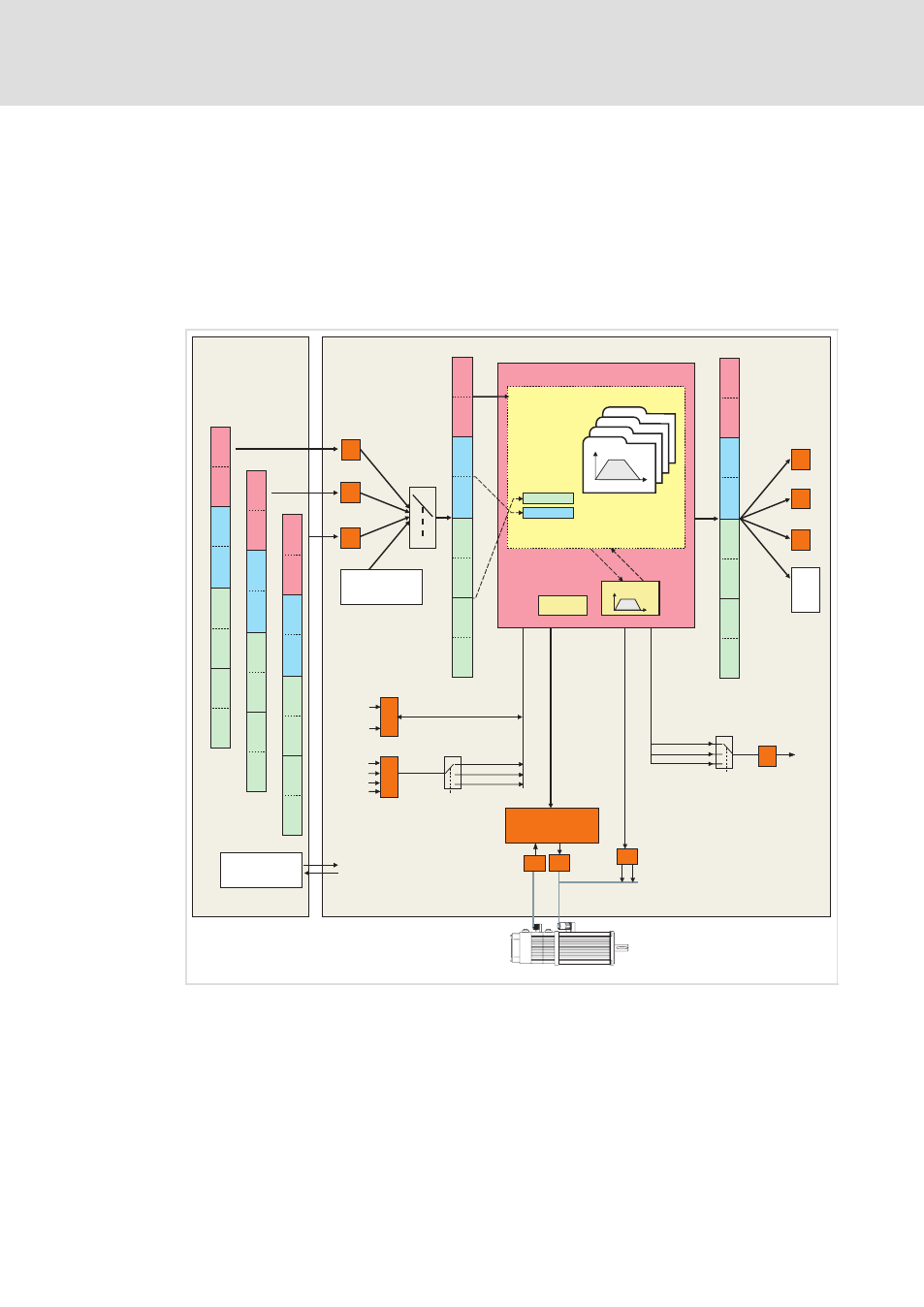
Device structure and interfaces to the higher−level control
The ECSxP axis module with the "Posi and Shaft" application program requires a
higher−level control (e. g. Lenze Drive PLC) for the coordination of the positioning process.
The "Posi and Shaft" application program enables input and storage of individual
positioning profiles and the accompanying profile parameters (target position, traversing
speed, acceleration, etc.). The selection, starting and timely sequencing of the positioning
profiles must be carried out by a higher−level control.
Profile 15
Profile ...
Profile 2
Profile 1
v
t
Direct modes
Control word:
Profile No.
Cinh
Jog CW
Jog CCW
TRIP-RESET
...
Prof enable
Homing
Manual operation
Point to point positioning
Touch probe positioning
EShaft
Brake logic
Positioning Control
Profiles
ECSxP
Customer PLC
Motor
Control
DigIn
DFIN
X6/DI1
Digital
frequency
X7
X6/DI2
X6/DI3
X6/DI4
DigOut
Internal relay
X6/DO1
X25/B1
X25/B2
DigIn mapping
DigOut mapping
AuxProfileBusy
Profile data
ProfEnable
C4012
C4011
C4010
PosProfiler
Byte
1
Byte
1
Byte
1
Byte
1
Byte
1
Byte
1
Byte
1
Byte
1
Byte
1
Byte
1
Byte
2
Byte
2
Byte
2
Byte
2
Byte
2
Byte
2
Byte
2
Byte
2
Byte
2
Byte
2
Byte
3
Byte
3
Byte
3
Byte
3
Byte
3
Byte
3
Byte
3
Byte
3
Byte
3
Byte
3
Byte
3
Byte
4
Byte
4
Byte
4
Byte
4
Byte
4
Byte
4
Byte
4
Byte
4
Byte
5
Byte
5
Byte
5
Byte
5
Byte
5
Byte
5
Byte
5
Byte
5
Byte
5
Byte
6
Byte
6
Byte
6
Byte
6
Byte
6
Byte
6
Byte
6
Byte
6
Byte
6
Byte
7
Byte
7
Byte
7
Byte
7
Byte
7
Byte
7
Byte
7
Byte
7
Byte
7
Byte
8
Byte
8
Byte
8
Byte
8
Byte
8
Byte
8
Byte
8
Byte
8
Byte
8
Control
word
Control
word
Control
word
Control
word
Process data Out
Process data In
Process
data
channel
S
tatus
word
1
S
tatus
word
2
1
:
2
n
0
0
X8
X6
X24
X25
X7
CAN-Out
CAN-AUX-Out
AIF-Out
X14
C4045
C4046
...
C4050
X1
Digital
frequency
Encoder
simulation
X4
C4040 AppControl
C4041 AppWord 2
C4042 AppWord 3/4
Parameter data
channel
X6
CAN-In
CAN-AUX-In
AIF-In
X14
X1
X4
ECSXA400
Fig. 6−14
Structure of ECS "Posi and Shaft"