11 electrical shaft ("eshaft"), Electrical shaft ("eshaft"), Commissioning – Lenze ECSCPxxx User Manual
Page 107
Commissioning
Basic terms of positioning
Electrical shaft ("EShaft")
l
107
EDBCSXP064 EN 8.0
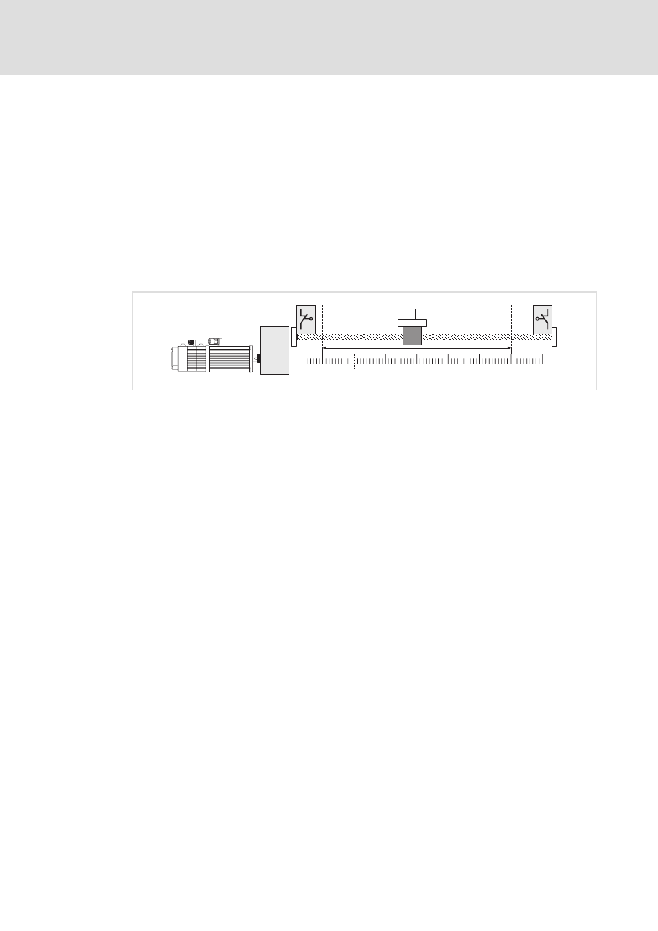
Software limit positions (C3040/C3041)
As well as defining the zero position it is important to define the limits of travel range to
avoid damages of the system, e. g. at manual control. These limits (limit switches/limit
positions) can be defined by hardware and software:
ƒ
Hardware limit switches are linked with the digital inputs of the controller; when
being activated, a certain action is carried out (e. g. quick stop).
ƒ
Software limit positions additionally limit the possible travel range within the
hardware limit switches and check on the drive level whether a position can be
approached.
Information on the operating mode and setting of the software limit positions can be
found on
^ 237.
0-Position
10
20
30
40
50
60
-10
ECSXA411
Fig. 6−13
Example: Limit positions of a linear positioning axis with spindle
Negative hardware limit switch
Negative software limit position, C3041 = −10 units
Positive software limit position, C3040 = +50 units
Positive hardware limit switch
6.1.11
Electrical shaft ("EShaft")
The "electrical shaft" drive function is used for line drives when several drives are to be
traversed with synchronous phase angle and speed, for instance, because they act upon
the same web. Via an adjustable stretch factor, the web tension can be varied between the
contact points of the drives at the web.
Detailed information on the configuration of the "Electrical shaft" drive function can be
found from
^ 211.