Commissioning – Lenze ECSCPxxx User Manual
Page 109
Commissioning
Basic terms of positioning
Device structure and interfaces to the higher−level control
l
109
EDBCSXP064 EN 8.0
The following control interfaces are available for the controller under code C4010:
ƒ
Automation interface (AIF) X1
– 4 process data words (in conjunction with the EMF2192IB EtherCAT
communication module, sync−controlled via the terminal X6/DI1)
ƒ
MotionBus (CAN) connection X4
– CAN1 (process data object 1, PDO1, sync−controlled)
– CAN3 (process data object 3, PDO3, cyclic)
ƒ
System bus (CANaux) connection X14
– CANaux1 (process data object 1, PDO1, sync−controlled)
– CANaux2 (process data object 2, PDO2, cyclic)
ƒ
Control via codes C4040, C4041, C4042 through a parameter data channel, e.g. AIF,
CAN, CAN−AUX, LECOM (for commissioning and test purposes)
The interface between the control and the ECSxP axis module is mainly determined by the
control word (Ctrl1) and the two status words (Stat1) and (Stat2). They contain all control
and status bits required for controlling the process.
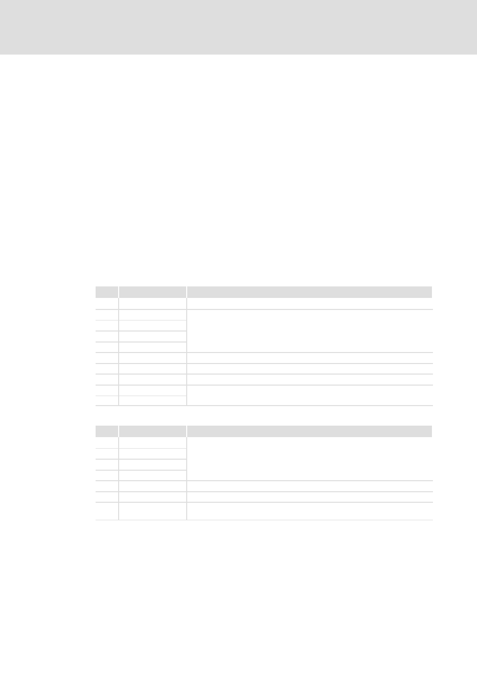
The most important control bits from the control: (
¶ 158):
Bit
Designation
Function
3
Quick stop (QSP)
Quick stop
4
PNoSet_1
Selection of the positioning profile (binary coded)
5
PNoSet_2
6
PNoSet_4
7
PNoSet_8
8
ProfEnable
Start of the selected positioning profile
9
CINH
Controller inhibit
11
TripReset
Reset fault message
12
JogCCW
Manual jog (inching mode)
13
JogCW
The most important status bits ("Stat1") to the control (
¶ 161):
Bit
Designation
Function
6
PNoAct_1
Feedback of the currently active positioning profile (binary coded)
7
PNoAct_2
8
PNoAct_4
9
PNoAct_8
13
HomePosAvailable
Home position known
14
InTarget
Positioning target reached
15
DwellTime
The dwell time has expired after profile generator setpoint has reached the
target position.