Commissioning – Lenze ECSCPxxx User Manual
Page 171
Commissioning
Configuring the digital inputs and outputs
Digital inputs for operation with linear positioning axis
l
171
EDBCSXP064 EN 8.0
6.14.2
Digital inputs for operation with linear positioning axis
Set C4011 = 0 in the parameter menu of the GDC under Short setup
W Digital I/Os.
Assignment of the inputs X6/DI1 ... DI4 when C4011 = 0:
Digital input
Function
Description
DI1
Negative limit switch
LOW level active
DI2
Reference switch
HIGH level active
DI3
Touch probe (TP)
HIGH level active
DI4
Positive limit switch
LOW level active
The following overview shows the assignment of C4011 = 0.
Ref
TP
Z2
CAN-AUX
Z1
1
2
3
4
5
7
6
8
9
:
;
<
DI1 DI2 DI3 DI4
ECSxP / ECSxA
X6
X24
X7
X14
R
0
L
ECSXA401
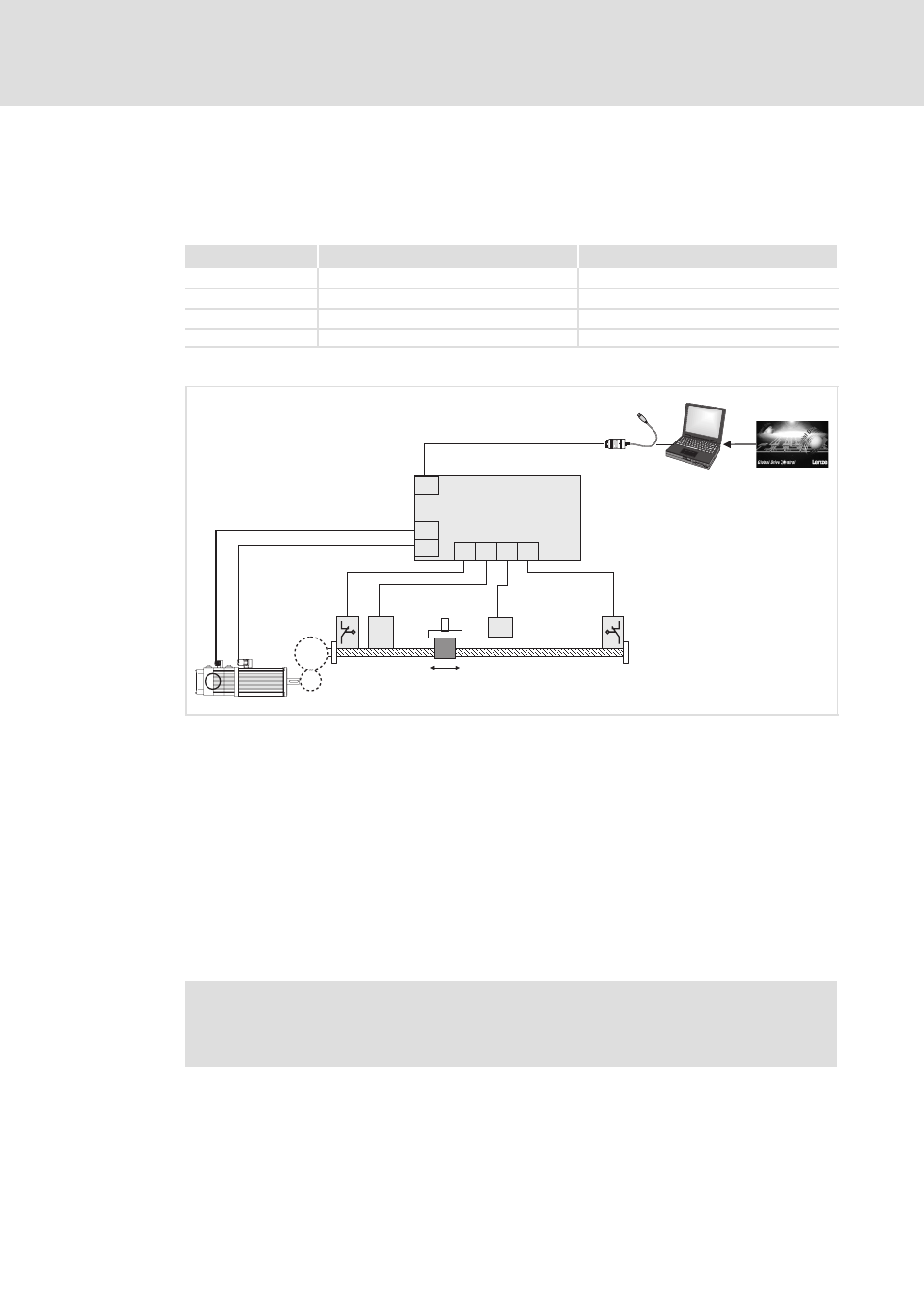
Fig. 6−30
Overview − linear positioning axis
0 PC system bus adapter (EMF2173IB/2177IB) with connecting cable
1 PC/laptop
2 Lenze parameterisation program "Global Drive Control" (GDC)
3 ECSxP or ECSxA axis module with "Posi and Shaft" application program
4 Speed / position feedback
5 Motor power connection
6 Servo motor with resolver feedback
7 Gearbox with transmission ratio i = Z2 / Z1 (ratio of the tooth numbers or circumferences) or
i = n1/n2 (ratio of the speeds)
8 Negative hardware limit switch
9 Reference switch
: Kinematics with limited travel range (spindle, linear unit)
; Touch probe sensor
< Positive hardware limit switch
)
Note!
The assignment of further control and power connection is described in
chapter "Electrical installation" (
¶ 48).