Commissioning – Lenze ECSCPxxx User Manual
Page 217
Commissioning
Configuring the electrical shaft ("E−Shaft")
Electrical shaft via MotionBus (CAN) with ECSxP as electrical shaft master
l
217
EDBCSXP064 EN 8.0
6.18.3
Electrical shaft via MotionBus (CAN) with ECSxP as electrical shaft master
X
S
X4
X14
X4
X14
X4
X14
X4
X14
120
120
120120
120120
E-Shaft Master
Slave 3
Slave 2
Slave 1
PLC
ECS
ECS
ECS
ECS
ECSXP002
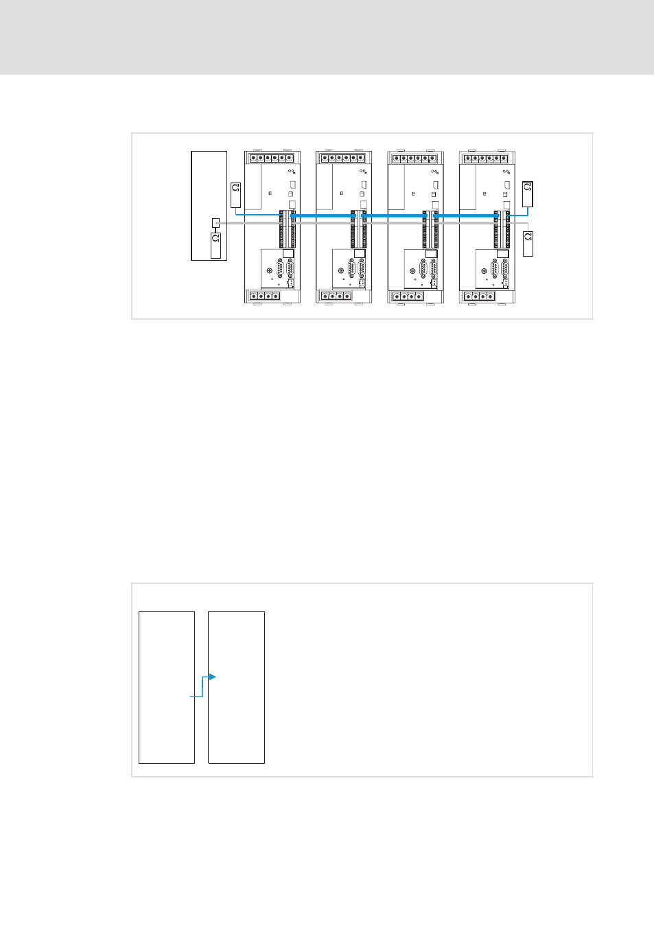
Fig. 6−52
Electrical shaft via MotionBus (CAN), control via system bus (CAN)
PLC
Master control (PLC) or a PLC device to control the drive system
E−shaft master Master value master (axis module ECSxP)
Slave 1 ... 3
Slave drives (ECSxP axis modules )
The following special features apply to the master value transmission per MotionBus
(CAN) X4 between master and slave/slaves:
ƒ
The master transmits the master values per process data channel 2 (PDO2−OUT) and
the slaves receive these via the process data channel 1 (PDO1−IN).
ƒ
For acceptance of the data of PDO1 in the slaves, the reception of a CAN sync
telegram is required. The CAN sync telegram is transmitted by the master.
ƒ
In this configuration with an ECSxP axis module as frequency master, the slave
drives do not return any status telegrams back to the master via the MotionBus
(CAN) at (X4).
ƒ
The control and coordination of the master control (PLC) is executed via the system
bus (CAN) at X14. Here, the control and status information are exchanged
accordingly.
E-Shaft
Master
E-Shaft
Slave 1 ... n
ECS
ECS
CAN1-Out
CAN2-Out
CAN3-Out
CAN1-In
CAN2-In
CAN3-In
ECSXP006
Fig. 6−53
MotionBus (CAN) telegram structure
Commissioning steps for a mimimum configuration
The codes can be found in the GDC in the "Positioning/E−shaft" menu item.