10 machine parameters, Machine parameters, Commissioning – Lenze ECSCPxxx User Manual
Page 103
Commissioning
Basic terms of positioning
Machine parameters
l
103
EDBCSXP064 EN 8.0
6.1.10
Machine parameters
A positioning process requires the machine parameters to convert the entries in the
application units into a device−internal incremental representation (inc). The GDC contains
the codes for setting the machine parameters in the parameter menu under Positioning
W
Machine parameters. (
¶ 165)
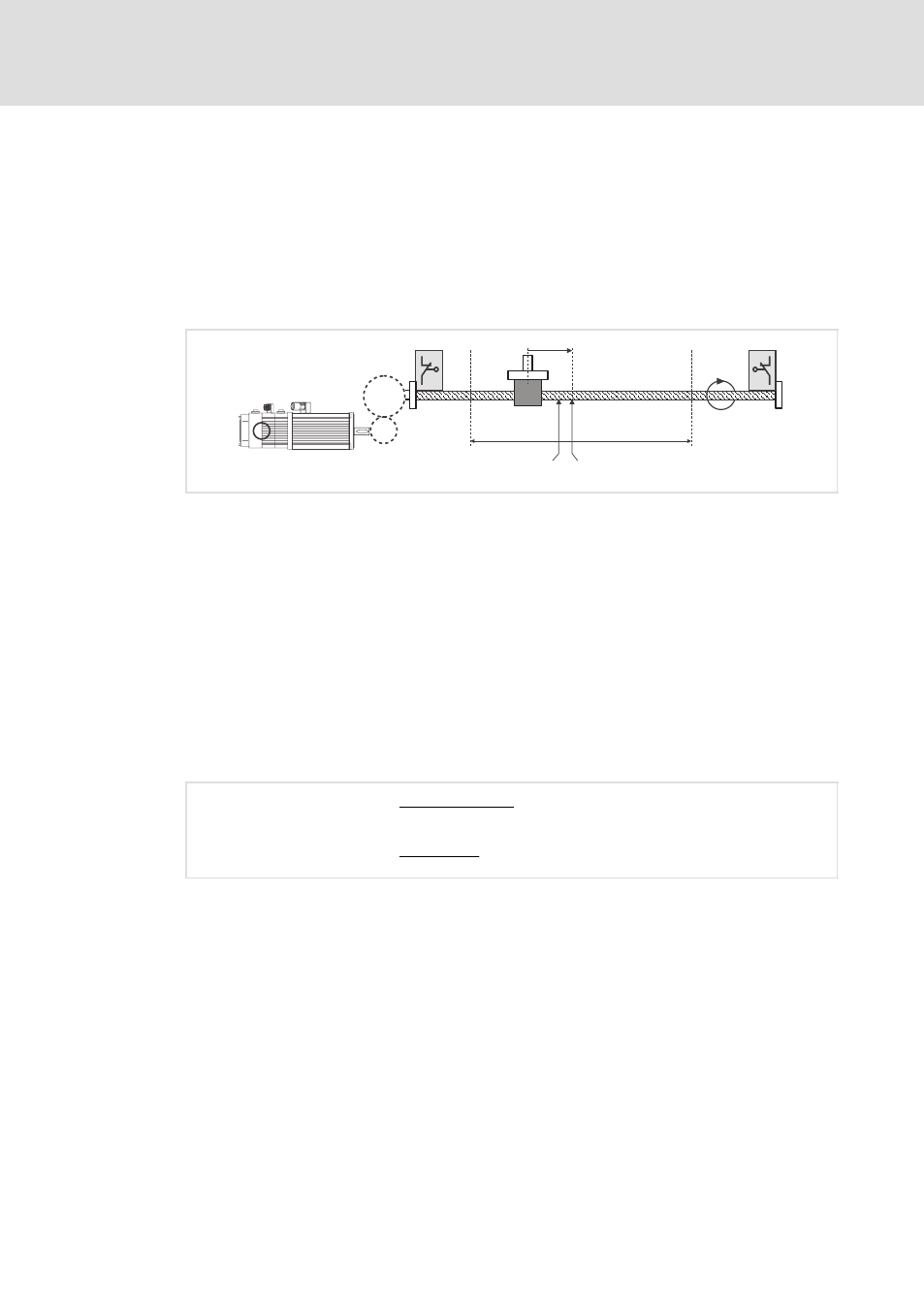
The machine parameters are explained in detail considering as example the operation of
a linear positioning axis with spindle which is provided with a movable slide:
Zero position
3000 mm
-2000 mm
i = 12.39
h = 20
s = 1000 mm
Target position
Z2
Z1
R
ECSXA417
Fig. 6−12
Example: Linear positioning axis with spindle
Motor/encoder
Gearbox with transmission ratio i = Z2 / Z1 (ratio of the tooth numbers or circumferences) or
i = n1/n2 (ratio of the speeds)
Negative software limit position
Positive software limit position
Feed constant (in mm/revolution), h = leadscrew pitch
The parameters for the positioning profile (target position, traversing speed, acceleration
and deceleration) are specified in real units with regard to the slide (e. g. 1000 mm as
relative target position or distance).
Target position in number of motor revolutions or converted into increments
In order to move the slide exactly 1000 mm to the right, the motor must rotate a certain
number of times which results from the gearbox ratio (i) and the feed constant (h).
Motor revolutions
+ 1000 mm
20 mm
ńrev.
@ 12.39 + 619.5 revolutions
Motor revolutions
+
Path (s)
Feed constant (h)
@ Gearbox ratio (i)
When multiplying the number of revolutions by the fixed position resolution of
65536 incr/rev. you obtain the distance to be traversed with internal incremental
representation.