Commissioning – Lenze ECSCPxxx User Manual
Page 215
Commissioning
Configuring the electrical shaft ("E−Shaft")
Electrical shaft via classical digital frequency coupling (digital frequency input X8)
l
215
EDBCSXP064 EN 8.0
6.18.2
Electrical shaft via classical digital frequency coupling (digital frequency input X8)
X8
X8
X8
X8
0
1
1
1
E-Shaft Master
Slave 3
Slave 2
Slave 1
X
S
PLC
X4
X4
X4
X4
120
ECS
ECS
ECS
ECS
X1
X5
X2
X3
X4
EMF2132IB
120
120
X14
X14
X14
X14
120
120
120
ECSXP001
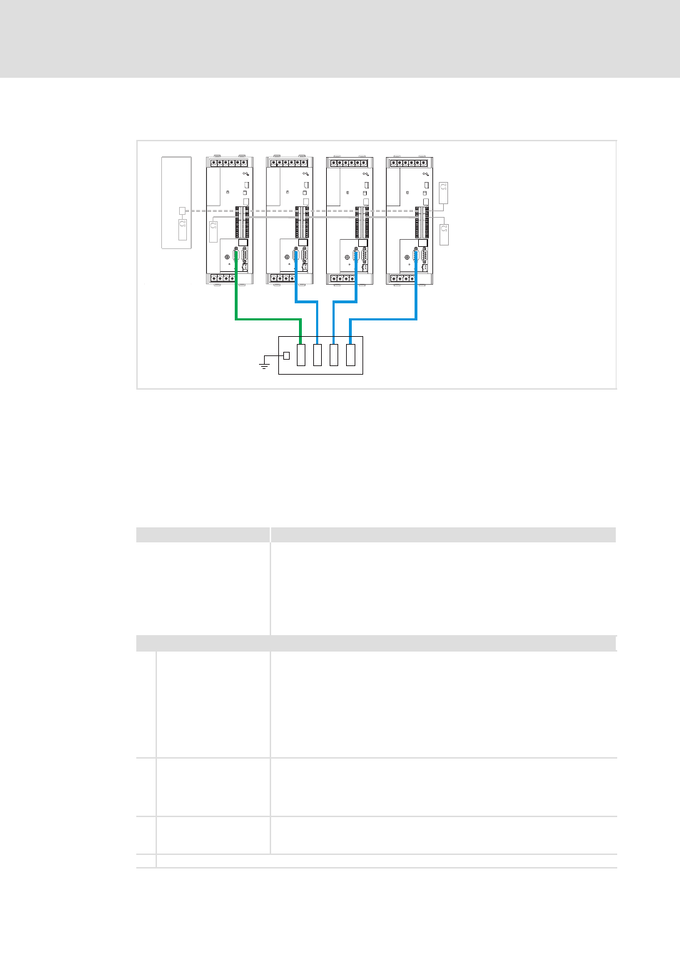
Fig. 6−51
ECS axis modules in the digital frequency network with digital frequency distributor EMF2132IB
PLC
Master control (PLC) or a PLC device to control the drive system
E−Shaft master Master value master (axis module ECSxP)
Slave 1...3
Slave drives (ECSxPaxis modules )
0
Master digital frequency cable EYD0017AxxxxW01W01 (socket/socket)
1
Slave digital frequency cable EYD0017AxxxxW01S01 (plug/socket)
Commissioning steps for a mimimum configuration
The codes can be found in the GDC in the "Positioning/E−shaft" menu item.
Setting
Brief description
Preconditions
l
Wiring of the digital frequency connection between interface X8 of the drive
controllers and the digital frequency distributor EMF2132IB
l
Wiring of the MotionBus (CAN) X4 for the control and coordination of the
drive system by the master control (PLC)
l
Connection of a PC via the "Global Drive Control" (GDC) operating program to
the system bus (CAN) X14 for parameterisation
l
Information on selection and configuration of the control interface to control
the drive system can be found on
^ 226.
Settings for the master drive
1.
Configure digital
frequency output.
l
C0491 = 1; configuration of signal direction at X8 = digital frequency output
l
C0540 = 1 or 2; set output function of X8
– 1: Digital frequency derived from setpoint (profile generator output)
– 2: Digital frequency derived from actual value (encoder simulation + zero
pulse)
l
C0030 = 2048; set DFOUT constant for the digital frequency output X8
– Standard setting: 2048 inc/rev
l
C0545 = 0 inc; set DFOUT angular offset
– Recommendation: 0 Inc
2.
Define positioning profile
for the operation.
l
Go to positioning profiles in the GDC parameter menu and create the
positioning profiles required for your application; e.g. with absolute
positioning or relative positioning in the continuous measuring system. (see
brief description
^ 123.)
l
Do not start the profiles yet!
3.
Save settings with mains
failure protection.
l
C0003 = 1; save parameter set 1 safe against mains failure.
The settings for the master drive are now completed.
4.
GDC: change to online connection to the slave drive.