Appendix – Lenze EVS9332xK User Manual
Page 452
Appendix
Code−oriented transfer mode
13.1
l
13.1−6
EDSVS9332K EN 8.0−07/2013
C1303/1
C1303/2
C1303/4
9300kur020
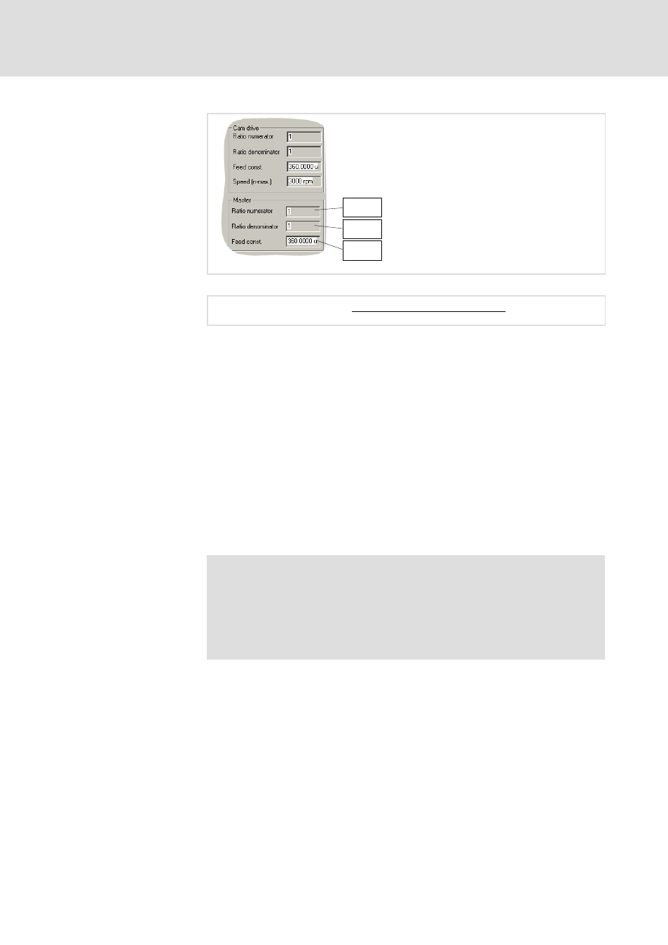
Fig. 13.1−6
Entry of the X coordinates in the "Basic settings" dialog box of GDC
XPOS [inc]
+ XPOS [m_units] @
65536 [inc
ńrpm] @ C1303ń1
C1303
ń4 [m_unitsńrpm] @ C1303ń2
XPOS
Target position
C1303/1
Gearbox numerator
C1303/2
Gearbox denominator
C1303/4
Feed constant
ƒ Enter all values in [inc].
ƒ A change of the profile clock pulse (last X value) will only be accepted
with the next clock pulse (profile cycle).
ƒ The 1st X value of a profile (C0392/1 and C0396/1) is always 0. All
other values will be rejected with NAK.
ƒ The X values have to be entered in ascending order, otherwise the
entries will be rejected with NAK.
Example: X1 < X2 < X3 < X4 < X5 < X6 < X7 < ...
ƒ Permissible value range: 0 ... +2
31
)
Note!
Changing the X coordinates online only makes sense for a few
applications. Generally, the distribution of the interpolation
points over the X coordinates is already specified when defining
the profile. This serves to set more interpolation points in critical
areas than in less critical areas.
X coordinates (master drive)