Commissioning, Hmi gdc – Lenze EVS9332xK User Manual
Page 233
Commissioning
Commissioning examples
Multi−axis application
6.14
6.14.2
l
6.14−3
EDSVS9332K EN 8.0−07/2013
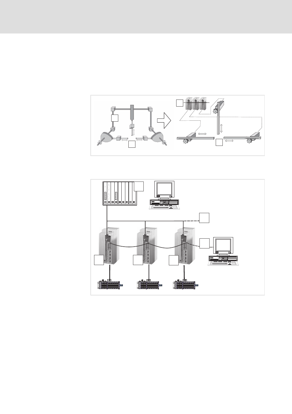
ƒ The line shaft is the connecting element between mechanical cams.
ƒ With the 9300 servo cam profiler the connection between the drives is
implemented via the system bus (CAN):
– The motion sequence of the communicating drives resulting from the
workpiece to be manufactured is identical.
– The user benefits from a very flexible machine concept.
A
B
B
A
Fig. 6.14−2
Comparison between mechanical and electronic cam
0
Workpiece to be machined
1
Line shaft
HMI
GDC
F
E
D
B
A
C
Fig. 6.14−3
Networking of master drive and slave drives via the system bus (CAN)
0
Machine control (PLC or IPC)
1
Fieldbus
2
System bus (CAN)
3
Master drive (virtual line shaft)
4
Slave drive
5
Slave drive
Description