Wiring of the standard device – Lenze EVS9332xK User Manual
Page 147
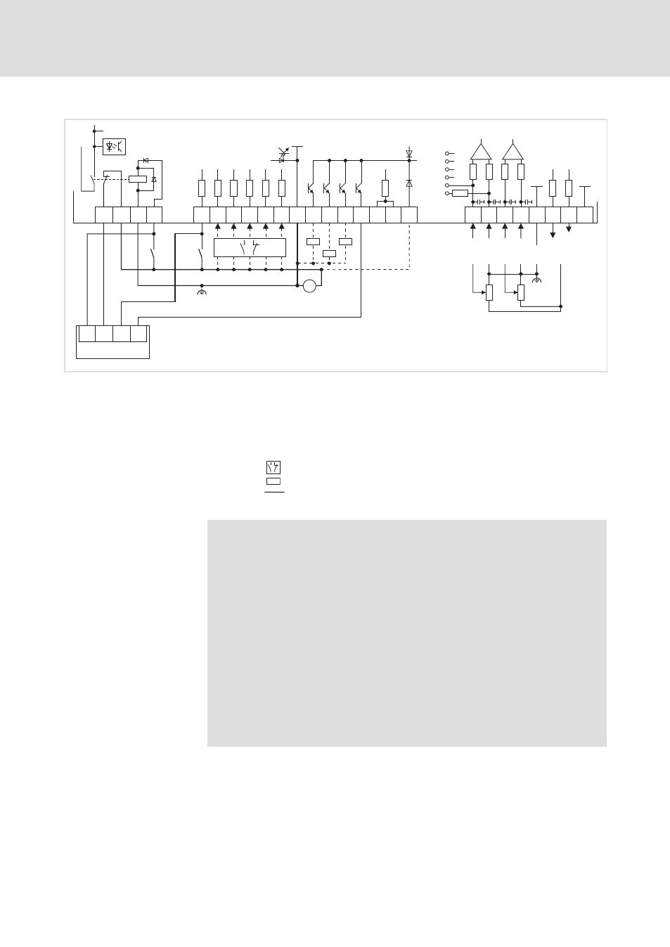
Wiring of the standard device
Control terminals
Device variant with "Safe torque off" function
5.8
5.8.4
l
5.8−7
EDSVS9332K EN 8.0−07/2013
Supply via external voltage source
X3
GND1
GND1
X6
1
2
3
4
7
7
62 63
242R
1
2
3
4
5
6
100k
100k
100k
100k
3.3nF
GND2
+24V
+5 V
E5
A2 A3 A4 ST1ST2 59
39
3k
47k
50mA
50mA
50mA
50mA
X5
28 E1 E2 E3 E4
3k
3k
3k
3k
3k
DC 24 V
(+18 V … +30 V)
X11 K31 K32 33 34
S1
S2
IN1 IN2 IN3 IN4
+
K
SR
+
–
A1
Z1
AIN1
AIN2
AOUTx
AOUT2
AOUT1
1
3
2
4
7
10k
10k
Z
Z
Z
9300std075
Fig. 5.8−6
Wiring of digital and analog inputs/outputs with active "Safe torque off" function
and external voltage source
S1
Deactivate pulse inhibit (1st disconnecting path)
S2
Enable controller (2nd disconnecting path)
Z1
Programmable logic controller (PLC)
The PLC monitors the ˜Safe torque off˜ function
X5/A4 Feedback via a digital output (e. g. DIGOUT4)
NO contact or NC contact
Z
Load
Minimum wiring required for operation
Terminal assignment in the Lenze setting:
^ 5.8−9
)
Note!
Supplying the digital inputs via an external voltage source
enables a backup operation in the case of mains failure. After
switching off the mains voltage, all actual values are continued
to be detected and processed.
ƒ
Connect the positive pole of the external voltage source with
X5/59 to establish the backup operation in the event of mains
failure.
ƒ
The external voltage source must be able to supply a current
³ 1 A.
ƒ
The starting current of the external voltage source is not
limited by the controller. Lenze recommends the use of
voltage sources with current limitation or with an internal
impedance of Z > 1
W.