Spinner spreader controller settings, Controller settings - spinner spreader, Pinner – Ag Leader EDGE Ver.4.5 Users Manual User Manual
Page 160: Preader, Ontroller, Ettings
148
Choose the appropriate Direct Type according to the module’s
part number:
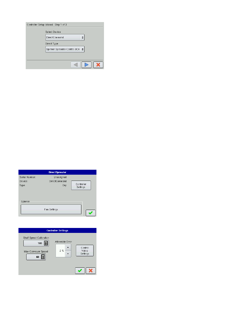
• 4000396 - Spinner Spreader Control 3 CH
• 4001611 - Spinner Spreader Control 5 CH
-a.Enter Suggested Controller Name. The display assigns a
default name of DirectSpreader to the controller. Use the on-
screen keyboard to edit the name if desired. Press Finish to
continue with the configuration process.
7. Select a Container
Select an existing container with the drop-down menu, or create a new one by pressing Add.
-a. Enter that container’s Capacity and Units. Use the numeric keypad to enter a capacity, and the drop-
down menu to enter in the type of units. Press the blue right-arrow button to continue.
-b. Enter Container Name and Location. Press Finish and you will return to the Operating Configuration
Wizard.
8. Select Ground Speed Source
Select Primary and Backup speed inputs from the drop-down menus. Press the blue right-arrow button to
continue.
9. Enter Suggested Configuration Name
The display combines the Vehicle and Controller names used during the setup process to use as the
Configuration name. Use the on-screen keyboard to edit name if desired. Press the checkmark box to
complete the setup wizard process.
S
PINNER
S
PREADER
C
ONTROLLER
S
ETTINGS
• Controller Settings
The Controller Settings button summons the Controller Settings
screen, which contains settings related to Shaft Speed Calibration,
Max Conveyor Speed, and Allowable Error. For more information,
see
“Controller Settings - Spinner Spreader” on page
• Fan Settings
For more information, see
Controller Settings - Spinner Spreader
• Shaft Speed Calibration
Calibration number representing the pulses that equal one
revolution of the rate control metering system.
• Max Conveyor Speed
Setting determines the maximum RPM of the conveyor that
controls product distribution to the application point.
• Allowable Error
Determines the percent of error that is allowed prior to the product
control system making any flow rate changes. 2% - 3% is the normal dead band setting range.
- Too low of a setting value can cause the product control system to continually hunt for the target
application rate.